Oblique incidence macro wafer inspection

a micro-wafer and micro-chip technology, applied in the direction of instruments, measurement devices, polarisation-affecting properties, etc., can solve the problems of large inspection machines, large fab space costs, and inability to match images

Inactive Publication Date: 2010-05-25
KLA TENCOR TECH CORP
View PDF10 Cites 21 Cited by
  • Summary
  • Abstract
  • Description
  • Claims
  • Application Information

AI Technical Summary

Problems solved by technology

The wafer motion during inspection causes problems in matching images.
Furthermore, the large parabolic mirrors used for collecting outgoing light have a large focal length, resulting in a very large inspection machine, which costs valuable fab space.

Method used


Image

  • Oblique incidence macro wafer inspection
  • Oblique incidence macro wafer inspection
  • Oblique incidence macro wafer inspection

Examples


Embodiment Construction

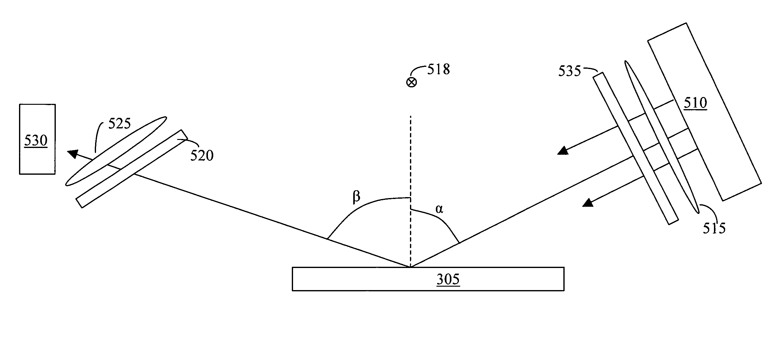
[0026]FIG. 3 shows a configuration used to test the sensitivity of defocus defects to detection under oblique incidence illumination. Sample 305 is illuminated from oblique angle α by illuminator 310, which is shown in this case to be a fluorescent light box. The light box has a heavy diffuser in front of the fluorescent tubes to provide uniform, diffuse illumination. The spectrum of the fluorescent illuminator consists primarily of the narrow spectral lines of Hg. Detector 315 is a conventional 2-dimensional color camera, in this case a commercial SLR Digital camera. The lens 320 and the detector 315 are tilted with respect to the sample surface according to the Scheimpflug configuration which allows the sample to stay in focus across the sample with oblique incidence illumination. The Scheimpflug geometry is discussed in U.S. Pat. No. GB 1196 / 1904, which is hereby incorporated by reference. A further analysis of the Scheimpflug geometry is found at http: / / www.trenholm.org / hmmerk / S...


PUM

PropertyMeasurementUnit
angleaaaaaaaaaa
angleaaaaaaaaaa
angleaaaaaaaaaa

Abstract

A line image acquisition apparatus suitable for being added onto a line-scan wafer macro-inspection system which incorporates oblique incidence illumination and detection, both for brightfield and for darkfield, which incorporates double darkfield observation capability, which incorporates broadly tunable angle of incidence illumination and tunable angle of detection, which incorporates multi-channel detection into a line-scan macro-inspection system, and which is an add-on feature compatible with current line-scan macro-inspection systems.

Description

CROSS REFERENCE TO RELATED APPLICATIONS[0001]This application corresponds to US Provisional Application No. 60,782,048, filed Mar. 14, 2006, and claims priority therefrom.FIELD OF THE INVENTION[0002]This invention relates to integrated circuit technology, and in particular to macro inspection of integrated circuit wafers.BACKGROUND OF THE INVENTION[0003]When performing macro inspection of integrated circuit wafers, several factors contribute to its effectiveness under varying circumstances. Included among these factors are the illumination angle, illumination intensity, angle of detection, polarization. The illumination and detection angles in particular affect observation in many ways. Brightfield observation occurs when the detected light is specularly reflected from the sample surface, i.e., when the angle of illumination and the angle of detection are the same. Brightfield inspection is useful for inspecting patterned regions with shallow topography, i.e., not much z variation. ...

Claims


Application Information

Patent Timeline
Patent Type & Authority Patents(United States)
IPC IPC(8): G01N21/00
CPCG01N21/956G01N21/9501G01N21/21G01N2021/8822
Inventor ROSENGAUS, ELIEZER
Owner KLA TENCOR TECH CORP
Why Eureka
Try Eureka