Four function surgical instrument

a surgical instrument and four-function technology, applied in the field of surgical instruments, can solve the problems of less than optimal cleaning of the instrument, borne disease transmission between patients, morbidity and mortality of surgical patients, etc., and achieve the effects of reducing frustration, reducing time consumption, and reducing the volum

Inactive Publication Date: 2010-06-01
INASURGICA
View PDF13 Cites 215 Cited by
  • Summary
  • Abstract
  • Description
  • Claims
  • Application Information

AI Technical Summary

Problems solved by technology

A leading cause of mortality and morbidity of surgical patients is hospital borne disease transmission between patients.
Despite the severity and rigor of these machines and procedures, the cleaning of the instruments is less than optimal.
Specifically, blood denatures and hardens in crevices or embeds onto restricted areas of an instrument such that there are deposits of blood that remain after cleaning.
The result being that there is a risk of the transmission of disease from patient to patient.
It is theorized that humankind will never be able to devise a machine and / or process that in an economical and practical manner will optimally clean surgical instrument.
The act of switching among these four instruments is time-consuming and can interrupt the surgeon's attention and concentration.
Alternating between these two instruments is time consuming and interrupts the surgeon's attention.
There is a need for a totally disposable instrument that is low in cost and avoids the transmission of pathogenic agents, because current sterilization techniques are not totally fail-safe.

Method used


Image

  • Four function surgical instrument
  • Four function surgical instrument
  • Four function surgical instrument

Examples


example 1

[0150]Example 1 is a proof of concept mockup of the instrument according to the present invention with a single plunger-like trigger. Referring to FIG. 5, this mock up had the principal parts, including, of a right housing, left cover, trigger, two pinch sliders, a Y-connector, a compression spring, two silicone tubes, a pipette tip and two metal tips.

example 2

[0151]Example 2 is an analysis of operational parameters of the proof of concept mockup of Example 1 (that is, a single plunger-like trigger and illustrated in FIG. 5.) The longitudinal travel distance on the trigger was 0.4 inches. In this mockup, the finger position felt natural and the travel distance was acceptable. Referring to FIG. 9B, the initial required force on the trigger was 28 ounces. As the trigger traveled, a pinch slider slides up a recess of a elongated slide surface of the trigger and concomitantly pinching close a silicone tube. The maximum force required on the trigger was 46.4 ounces. The required force ramps at a maximum of 42.90 degrees.

example 3

[0152]Example 3 is a proof of concept mockup of an instrument according to the present invention with a double plunger-like trigger. Referring to FIG. 7, it was constructed using silicone tubing having a 0.125 inch outside diameter by 0.063 inch inside diameter. The force to pinch close the silicone tubing with a 0.188 inch rod was 9.0 ounces. The force to pinch close the silicone tubing with a 0.128 inch rod was 7.5 ounces. The force to pinch close the silicone tubing with a 0.093 inch rod was 7.0 ounces. The compression at closure was approximately 0.045 inches.


PUM


Abstract

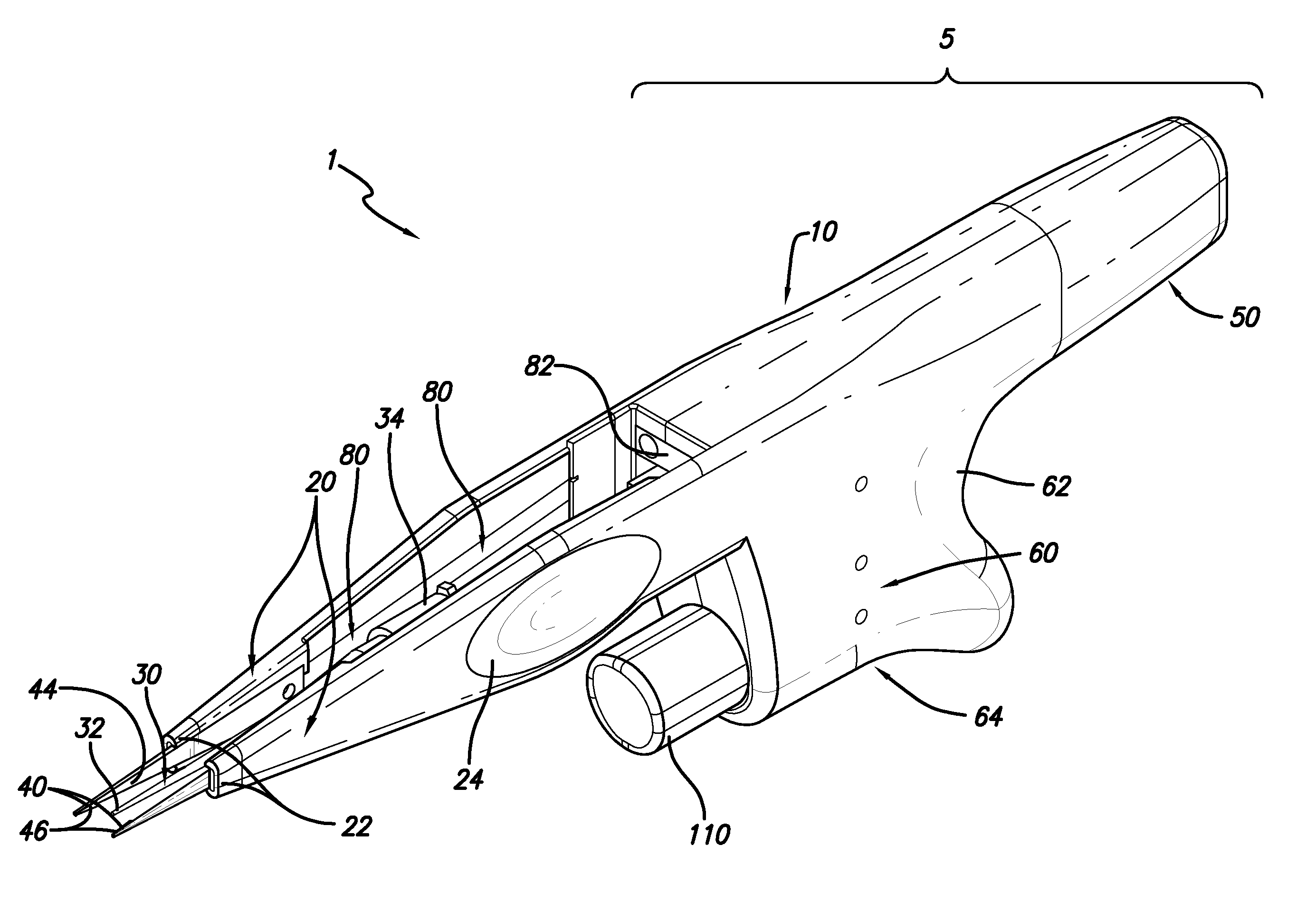
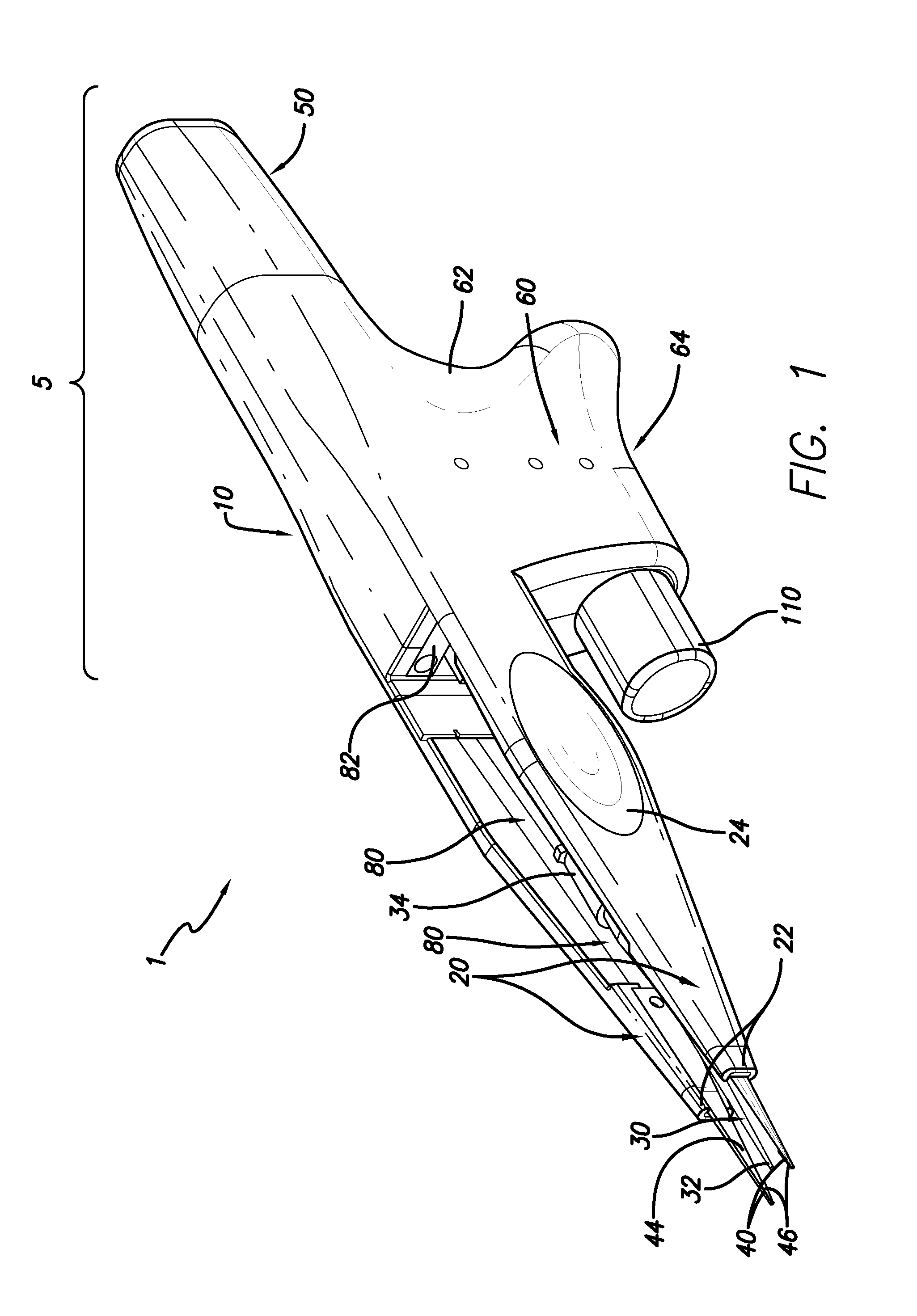
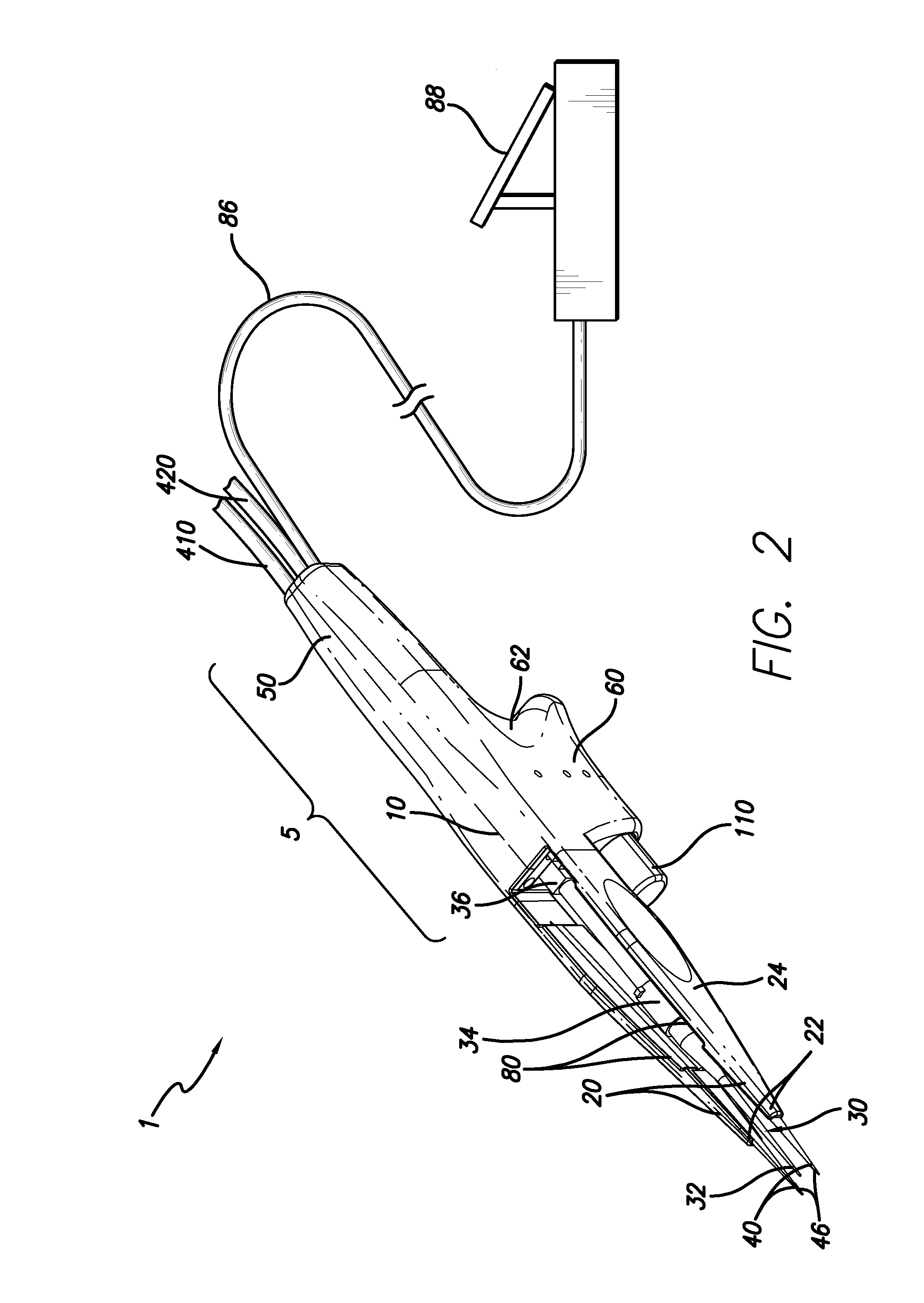
A unique four function surgical instrument that performs aspiration, irrigation, dilation and cauterization with an innovative trigger mechanism. An embodiment is “gun-like” in configuration having a housing with a depending handle and a protruding trigger, a forward extending pair of forceps-like arms that terminate in dilation / cauterization tips and a common conduit between the forceps-like arms. The unique trigger mechanism utilizes a pinch valve concept where the trigger button has an elongated portion that has two slide surfaces with offset a recesses that act like tracks on which pinch sliders follow and the pinch sliders act like valve stems that squeeze close and allow to open silicone tubing. The end result, being a single poll, two stage actuator such that a half a pump of the trigger delivers irrigation or aspiration and a full pump delivers the other. The instrument provides the advantages of small size, ergonomical and all-in-one so as to eliminate the need for a surgeon to fumble around in switching between instruments.

Description

CROSS-REFERENCE TO RELATED APPLICATIONS[0001]This application is a continuation-in-part of application assigned Ser. No. 11 / 471,067 that was filed Jun. 20, 2006 and the benefit this earlier filed application is claimed. Said earlier filed application in turn claims the benefit of a provisional application assigned Ser. No. 60 / 692,479 which was filed Jun. 21, 2005.BACKGROUND OF THE INVENTION[0002]1. Field of the Invention[0003]This invention is in the field of surgical instruments and more particularly in the field of vessel dilators.[0004]2. Related Art[0005]A leading cause of mortality and morbidity of surgical patients is hospital borne disease transmission between patients. There are many machines and procedures for sterilizing and cleaning surgical instruments, including autoclaving. Despite the severity and rigor of these machines and procedures, the cleaning of the instruments is less than optimal. Specifically, blood denatures and hardens in crevices or embeds onto restricted...

Claims


Application Information

Patent Timeline
Patent Type & Authority Patents(United States)
IPC IPC(8): A61N1/30A61B18/18
CPCA61B18/1442A61B2018/00595A61B2218/007A61B2218/002A61B2018/1462
Inventor BAYAT, ARDESHIR
Owner INASURGICA
Why Eureka
Try Eureka