
Pressurized bladder canister for installation of cured in place pipe

a pressure-filled bladder and pipe technology, applied in the direction of shaft lining, shaft equipment, mechanical equipment, etc., can solve the problems of near the pipe joint, and the deterioration of the pipe itsel

Inactive Publication Date: 2005-11-29
INA ACQUISITION
View PDF27 Cites 34 Cited by
  • Summary
  • Abstract
  • Description
  • Claims
  • Application Information

AI Technical Summary

Benefits of technology

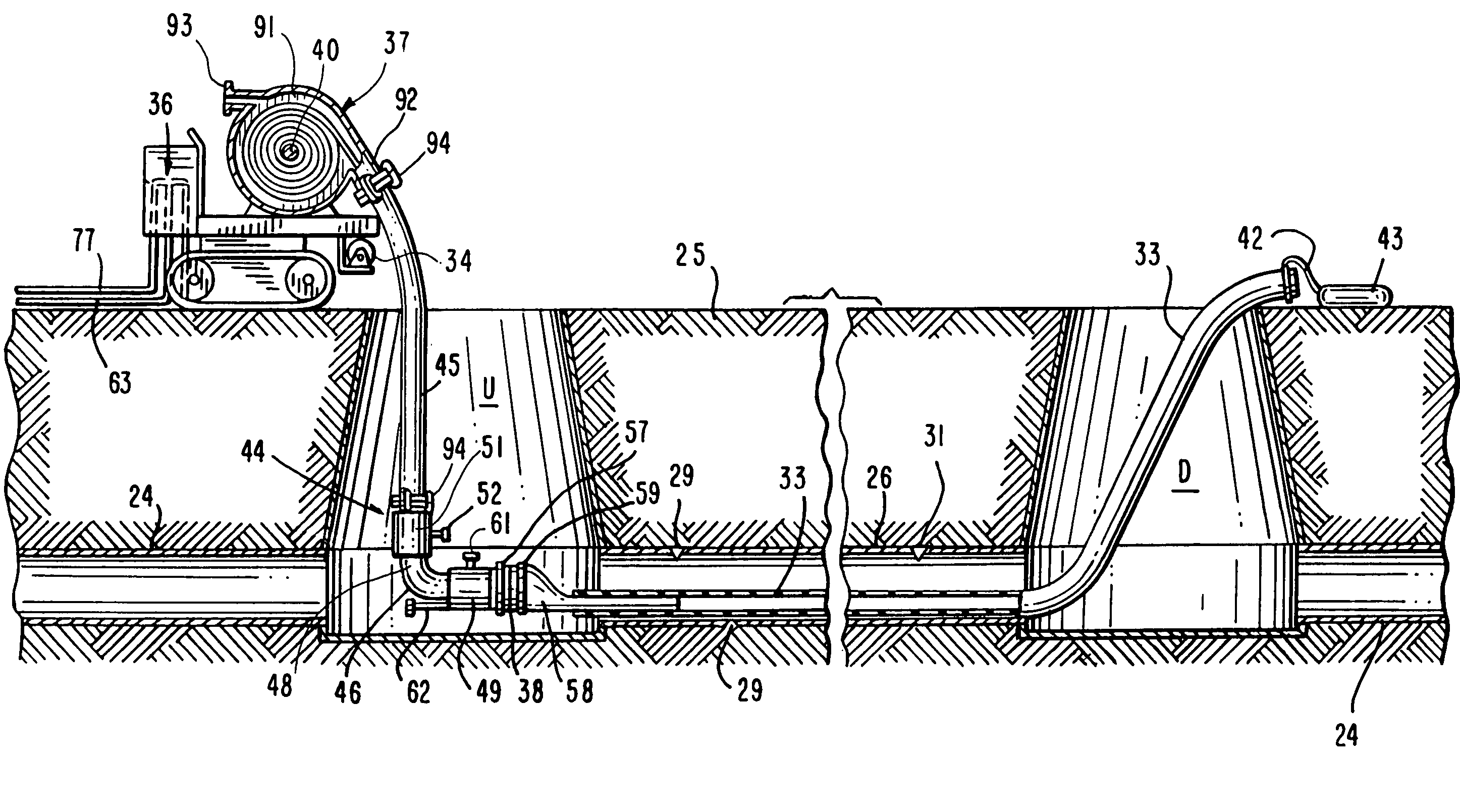
[0014]While maintaining pressure in the bladder canister and bladder, a pinch valve at the inlet side of the eversion elbow is closed. Steam is introduced into the elbow downstream of the valve and passes through the bladder to initiate the cure and exits through the canister exhaust. After the resin in the liner is cured, the steam is turned off and the air pressure is adjusted to maintain pressure in the bladder and maximize cooling. The valve is opened and the inflation bladder is then withdrawn by de-everting. Any condensate in the bladder is removed through a condensate trap in the elbow in the eversion manhole.
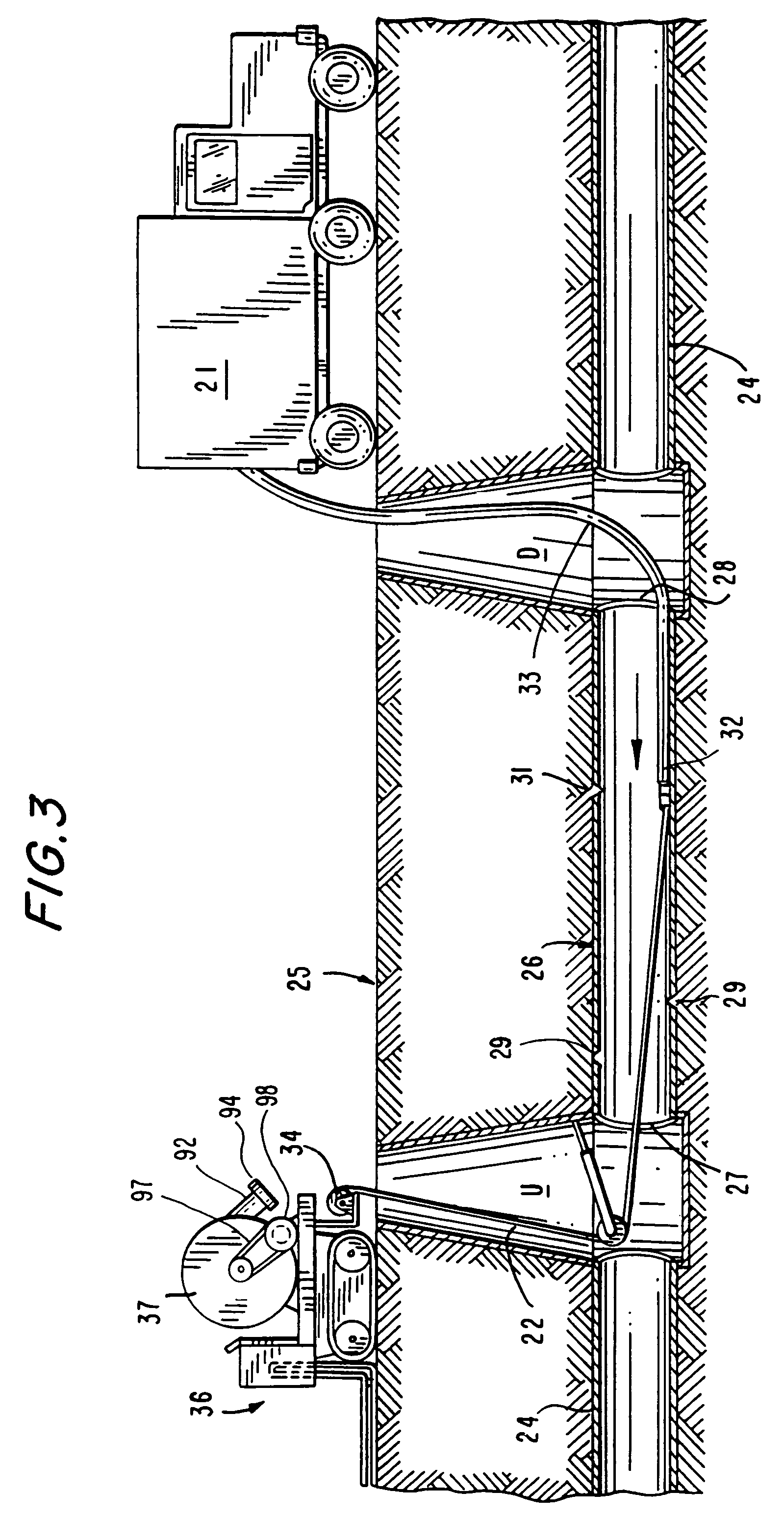
[0015]In a preferred embodiment of the invention, an easement vehicle carries a pressure bladder canister with a spooled inflation bladder of appropriate length on a staging spool mounted there in. The vehicle is positioned at the eversion access and includes valves and regulators for applying pressurized air to the canister for eversion of the bladder and steam for curing of the liner and removal of the bladder after cure. In a most preferred aspect of the invention, the inflation fluid is air which is introduced into the bladder canister for inflating the bladder. This allows the precise control of the speed of the everting bladder. After the bladder inflates the liner, it enters a receiving canister having a puncturing element positioned in the receiving manhole. The bladder is sealed against the canister wall and is punctured to allow air to exit through an exhaust port. The elbow valve is sealed about the bladder and steam is introduced at the eversion elbow. The steam flows through the bladder to cure the resin quickly and completely without loss of pressure in the bladder. This maintains hot curing fluids safely below ground, a safe distance away from any personnel.
[0017]Another object of the invention is to provide an improved method for pull in and inflate installation of a cured in place liner by introducing a pressurized eversion fluid into the a bladder canister to control eversion of the bladder.
[0019]Yet another object of the invention is to provide an improved method for pull in and inflate installation of a cured in place liner by introducing pressurized air as a eversion fluid into the a bladder canister to control eversion of the bladder.
[0020]It is a further object of the invention is to provide an improved method of installation of a cured in place liner by pull in and inflate wherein the bladder canister is isolated from the bladder canister by a pinch valve and steam as a curing fluid is introduced into the bladder to cure the resin.
[0021]Still another object of the invention is to provide an improved method for pull in and inflate installation of cured in place liner by automatically puncturing the bladder as it enters a receiving canister in the downstream manhole.

Problems solved by technology

It is generally well known that conduits or pipelines, particularly underground pipes, such as sanitary sewer pipes, storm sewer pipes, water lines and gas lines that are employed for conducting fluids frequently require repair due to fluid leakage.
The leakage may be due to improper installation of the original pipe, or deterioration of the pipe itself due to normal aging or to the effects of conveying corrosive or abrasive material.
Cracks at or near pipe joints may be due to environmental conditions such as earthquakes or the movement of large vehicles on the overhead surface or similar natural or man made vibrations, or other such causes.
Regardless of the cause, such leakages are undesirable and may result in waste of the fluid being conveyed within the pipeline, or result in damage to the surrounding environment and possible creation of a dangerous public health hazard.
If the leakage continues it can lead to structural failure of the existing conduit due to loss of soil and side support of the conduit.
Because of ever increasing labor and machinery costs, it is increasingly more difficult and less economical to repair underground pipes or portions that may be leaking by digging up and replacing the pipes.
While the pull in and inflate method has these advantages, the installation process is somewhat more complex than an eversion of the resin impregnated liner.
While the pull in and inflate method utilizing water does have the various advantages noted above, the shortcomings tend to increase labor costs which are a significant aspect of the installation process.

Method used


Image

  • Pressurized bladder canister for installation of cured in place pipe
  • Pressurized bladder canister for installation of cured in place pipe
  • Pressurized bladder canister for installation of cured in place pipe

Examples


Embodiment Construction

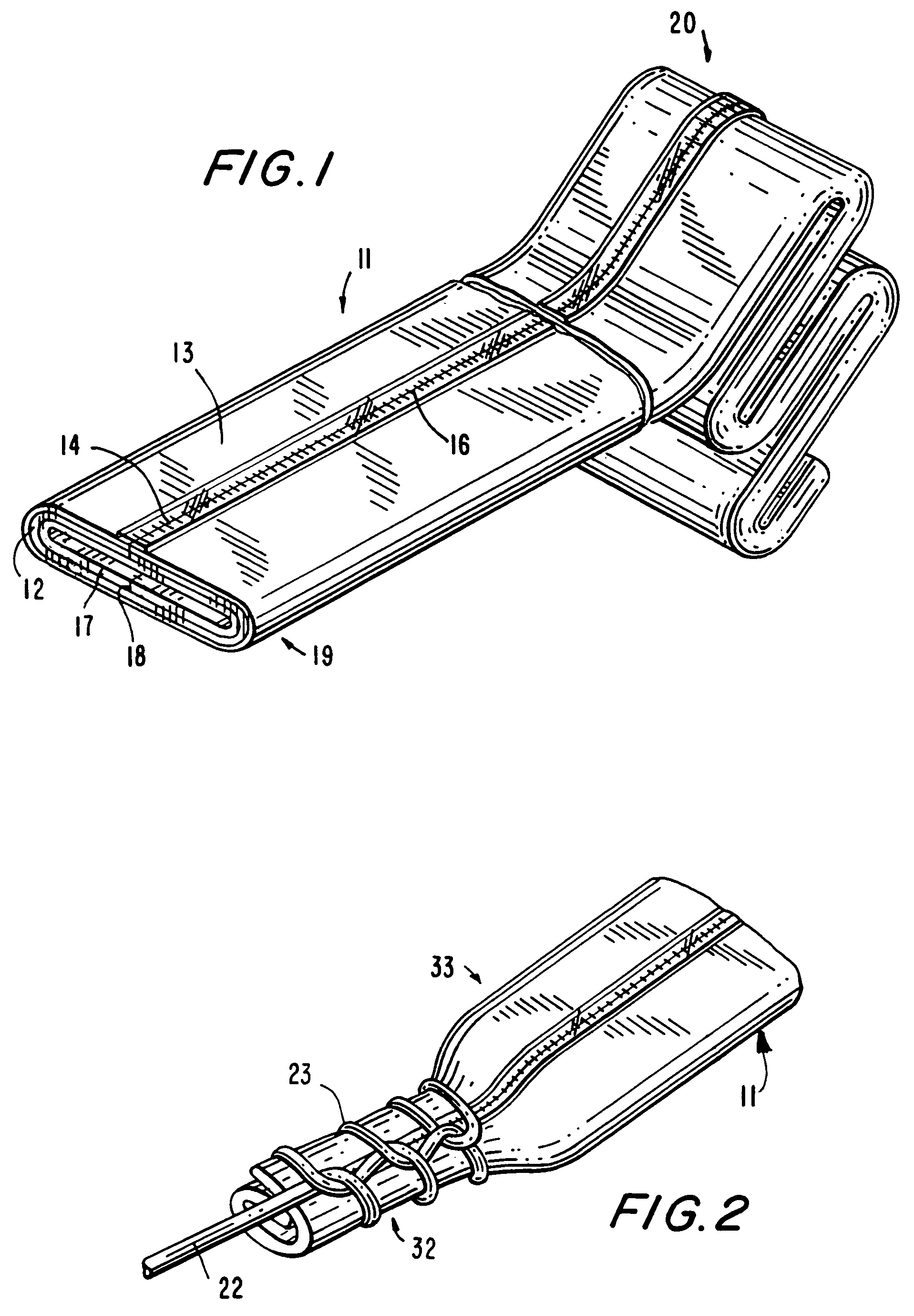
[0037]FIG. 1 illustrates a flexible cured in place liner 11 of the type generally well known in the art. Liner 11 is formed from at least one layer of a flexible resin impregnable material, such as a felt layer 12 having an outer impermeable polymer film layer 13. Felt layer 12 and film layer 13 are stitched along a seam line 14 to form a tubular liner. A compatible thermoplastic film in a form of a tape or extruded material 16 is placed on or extruded over seam line 14 in order to ensure the impermeability of liner 11. In the embodiment illustrated in FIG. 1 and used throughout this description, liner 11 includes an inner second felt layer 17 also stitched along a seam line 18 which is positioned at a point in the tube other than the location of seam line 14 in outer felt layer 12. Liner 11 has a leading end 19 with a continuous length stored in a refrigeration unit 21 (FIG. 3) to suppress early cure of the resin. Liner 11 is cut to a desired length after being pulled into the exis...


PUM

PropertyMeasurementUnit
Lengthaaaaaaaaaa
Pressureaaaaaaaaaa

Abstract

A process for lining an existing pipeline or conduit with a flexible resin impregnated cured in place liner by pulling in the liner and inflating an eversion bladder with air and curing the liner with flow-through steam without loss of pressure is provided. The bladder is stored in a pressure bladder canister coupled to a pressurized downtube and eversion elbow. The bladder is everted by introducing pressurized air into the canister As the bladder reaches the distal manhole, it enters a receiving canister where it is punctured while maintaining air pressure within the bladder a pinch valve between the downtube and elbow isolates the inverted bladder so that steam can be introduced into the bladder to cure the resin and exhaust through the receiving canister. The bladder is then removed and lateral service reinstated.

Description

CROSS-REFERENCE TO RELATED APPLICATIONS[0001]This application is a divisional of application Ser. No. 10 / 404,183, filed on Apr. 1, 2003, now U.S. Pat. No. 6,679,293 which is a continuation of application Ser. No. 10 / 098,974 filed on Mar. 14, 2002, now U.S. Pat. No. 6,539,979 issued on Apr. 1, 2003, which is a continuation of application Ser. No. 09 / 927,189, filed Aug. 10, 2001 now abandoned.BACKGROUND OF THE INVENTION[0002]This invention relates to a method for installation of a cured in place liner by pulling in and inflating the liner and more particularly to a method of trenchless rehabilitation of an existing conduit by pulling a resin impregnated liner into the existing conduit everting an inflation bladder stored in a pressurized bladder canister into the liner by introducing air into the canister, isolating the canister and introducing continuous flow-through steam into the bladder without loss of pressure in the bladder and to the apparatuses for practicing the method.[0003]...

Claims


Application Information

Patent Timeline
IPC IPC(8): F16L55/165
CPCF16L55/1651F16L55/1654B29C63/34
Inventor DRIVER, FRANKLIN THOMAS
Owner INA ACQUISITION
Learn More