Peristaltic pump with roller pinch valve control

a peristaltic pump and roller technology, applied in the direction of machines/engines, positive displacement liquid engines, pump parameters, etc., can solve the problems of large variation of the volumetric flow rate of a given pump motor rpm, repeated flattening and permanent deformation of the flow area, and high cost of pulling mechanisms

Active Publication Date: 2005-01-27
HEWLETT PACKARD DEV CO LP
View PDF3 Cites 39 Cited by
  • Summary
  • Abstract
  • Description
  • Claims
  • Application Information

AI Technical Summary

Benefits of technology

[0015]FIG. 7 is a schematic graphic ...

Problems solved by technology

During repeated starting and stopping of pump operation, the rollers will have stopped at positions along the entire arc of the roller/occlusion intersection, causing repeated flattening and permanent deformation of the flow area of the peristaltic ...

Method used


Image

  • Peristaltic pump with roller pinch valve control
  • Peristaltic pump with roller pinch valve control
  • Peristaltic pump with roller pinch valve control

Examples


Embodiment Construction

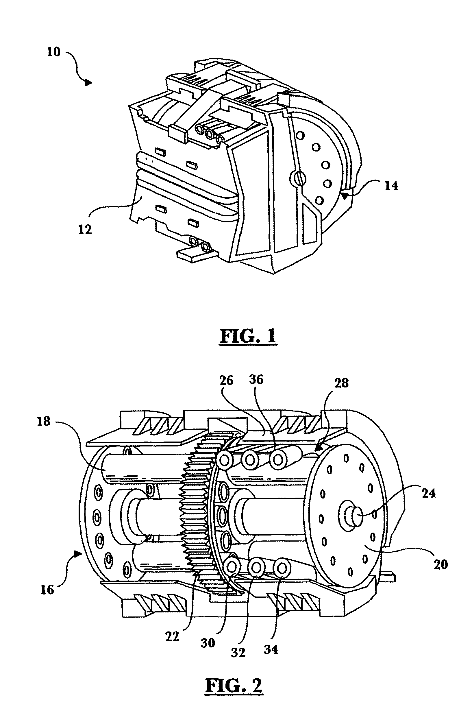
[0016] An exemplary embodiment of a peristaltic pump assembly 10 in accordance with the principles of the present invention is shown in FIG. 1. The pump assembly 10 is provided with an outer housing 12 enclosing a working portion 14. The housing 12 serves to protect the working portion 14 from its surroundings, and can also be configured to adapt the pump assembly 10 for fitting into the device in which it is installed. The pump assembly 10, as illustrated, is adapted and constructed to be employed in an imaging system, such as the ink supply system of an electronic printer. It is contemplated that the principles of the present invention are also applicable to any other system in which peristaltic pump having multiple flexible tubes is used.

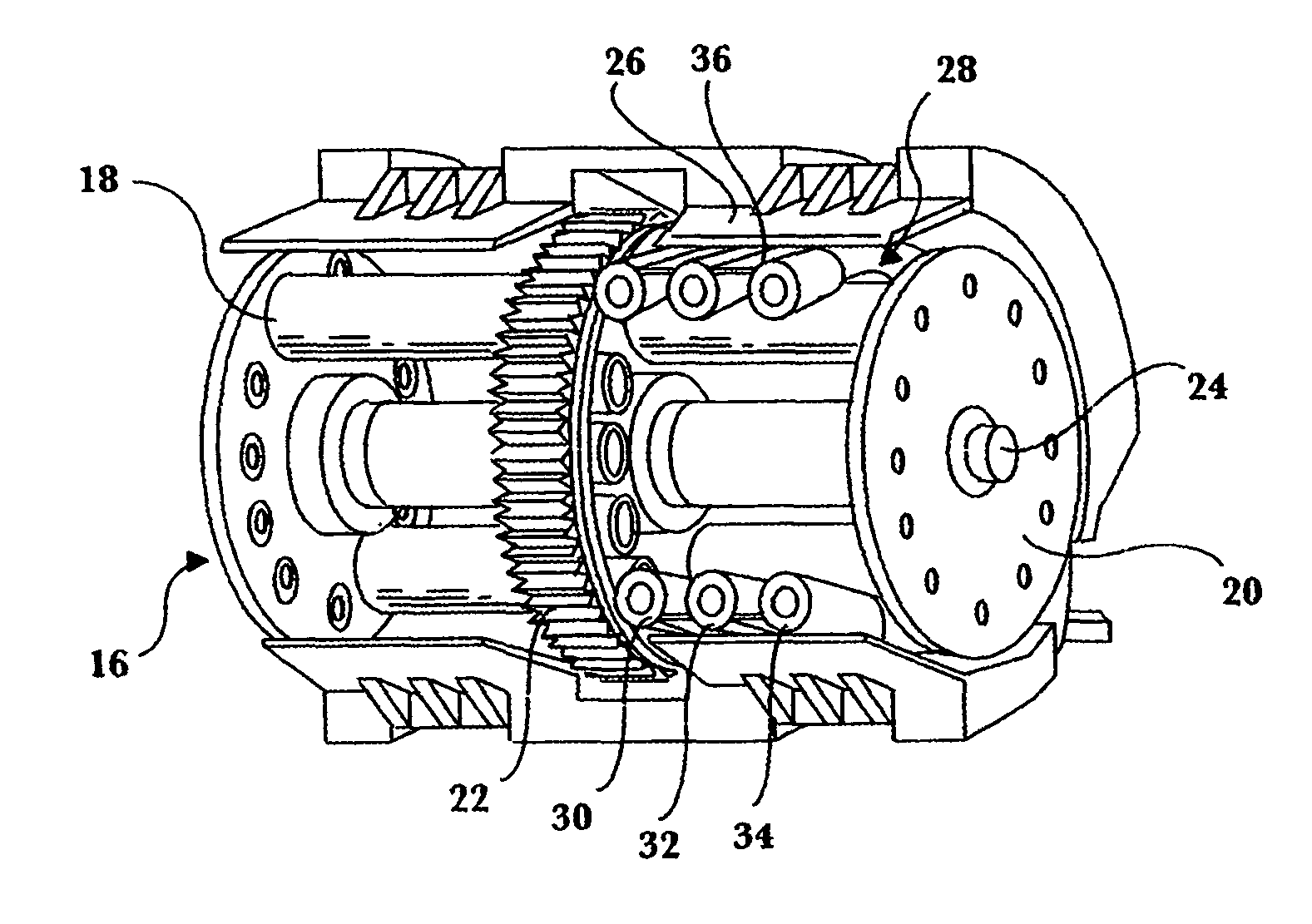
[0017] As shown in FIG. 2, the working portion 14 of the pump assembly 10 includes a rotor 16 having at least one roller, here provided as a pair of rollers 18, 20. The rollers 18, 20 are driven in a known manner for rotation about an axis 22.

[...


PUM


Abstract

A pump having a rotary portion which compels the movement of a fluid by peristaltic compression of resilient tubing containing the fluid includes a roller assembly having at least one roller mounted in the rotary portion of the pump for contact with the resilient tubing. The roller has a range of rotation in contact with the tubing during pump operation. A roller control mechanism is adapted and constructed to stop the roller at a single, predetermined location on the tubing when the pump operation is stopped.

Description

FIELD OF THE INVENTION [0001] The invention relates generally to the use of rollers for flow control in peristaltic pumps. BACKGROUND OF THE INVENTION [0002] Peristaltic pumps are used in a variety of applications in which it is desirable to convey fluid in accurately controllable quantities. Peristaltic pumps typically include a rotary portion which compels the movement of a fluid by peristaltic compression of resilient tubing containing the fluid against an arcuate rigid surface known as a pump occlusion. The roller / occlusion intersection area is typically known as the “working area” of the pump. [0003] Imaging systems using inkjet printing have become widely known, and are often implemented using thermal inkjet technology. Such technology forms characters and images on a medium, such as paper, by expelling droplets of ink in a controlled fashion so that the droplets land on the medium. The printer, itself, can be conceptualized as a mechanism for moving and placing the medium in ...

Claims


Application Information

Patent Timeline
IPC IPC(8): F04B43/12
CPCF04B43/1253F04B2201/1208F04B43/1292
Inventor OTIS, DAVID R. JR.
Owner HEWLETT PACKARD DEV CO LP
Why Eureka
Try Eureka