Floor drain installation system

a technology for installing systems and drains, which is applied in sewer cleaning, transportation and packaging, mechanical equipment, etc., can solve the problems of not being able to provide for drain and adaptor assembly adjustment, the need for further upward adjustment of drains, and the damage of drains

Active Publication Date: 2010-06-15
SIOUX CHIEF MFG
View PDF9 Cites 75 Cited by
  • Summary
  • Abstract
  • Description
  • Claims
  • Application Information

AI Technical Summary

Problems solved by technology

In addition, the drains are subject to damage from heavy loads rolled across the floor during construction of additional building structures.
Additional problems can arise when a layer of tile or other flooring material is installed over the concrete slab.
Unfortunately, it is not uncommon for concrete crews to mistakenly pour the slab to the top of the drains instead of the specified lower level, thereby creating the need for further upward adjustment of the drains.
Such adjustment is often not provided for by the drain and adaptor assembly.
In either case, once the concrete is poured around the drains and has set, it is usually impossible to raise or lower the drains (accomplished by turning them relative to the associated adaptor) without chipping away the concrete surrounding the drain to provide clearance for lugs usually formed on the bottom of the drain head and to break the adhesion between the concrete and the drain head surface.
Similarly, if the building owner later decides to add a layer of flooring over the slab or to substitute existing flooring with a thicker layer, it is usually impossible to raise the drains to the higher level without first chipping or breaking away the concrete from around the drain head.

Method used


Image

  • Floor drain installation system
  • Floor drain installation system
  • Floor drain installation system

Examples


Embodiment Construction

[0041]As required, detailed embodiments of the present invention are disclosed herein; however, it is to be understood that the disclosed embodiments are merely exemplary of the invention, which may be embodied in various alternative forms. Therefore, specific structural and functional details disclosed herein are not to be interpreted as limiting, but merely as a basis for the claims and as representative bases for teaching one skilled in the art to variously employ the present invention in virtually any appropriately detailed structure. As used herein, the term concrete is intended to include any material which can be poured and then sets or hardens to form a slab or the like, including a mixture of aggregate and Portland cement and aggregate and asphalt.

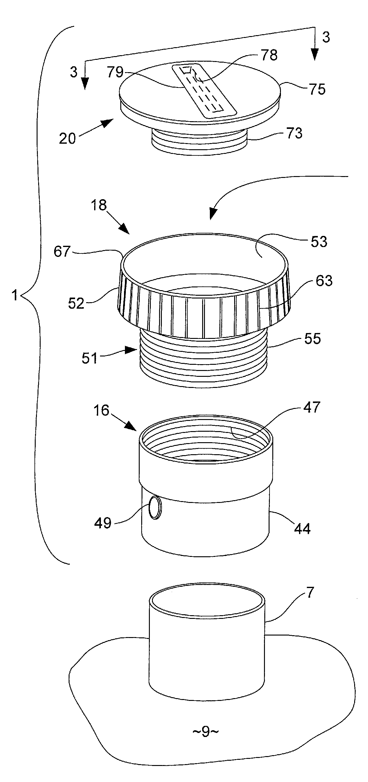
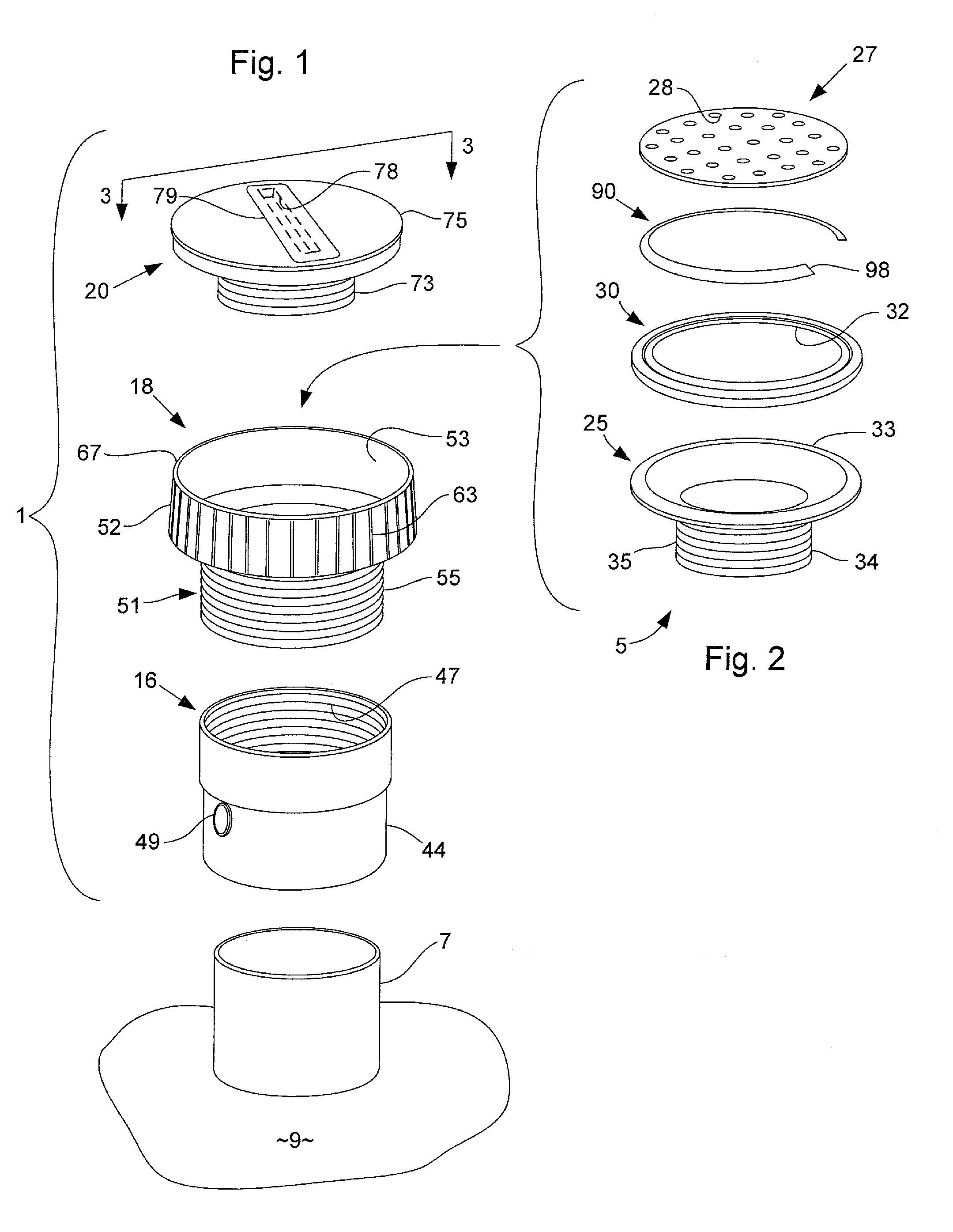
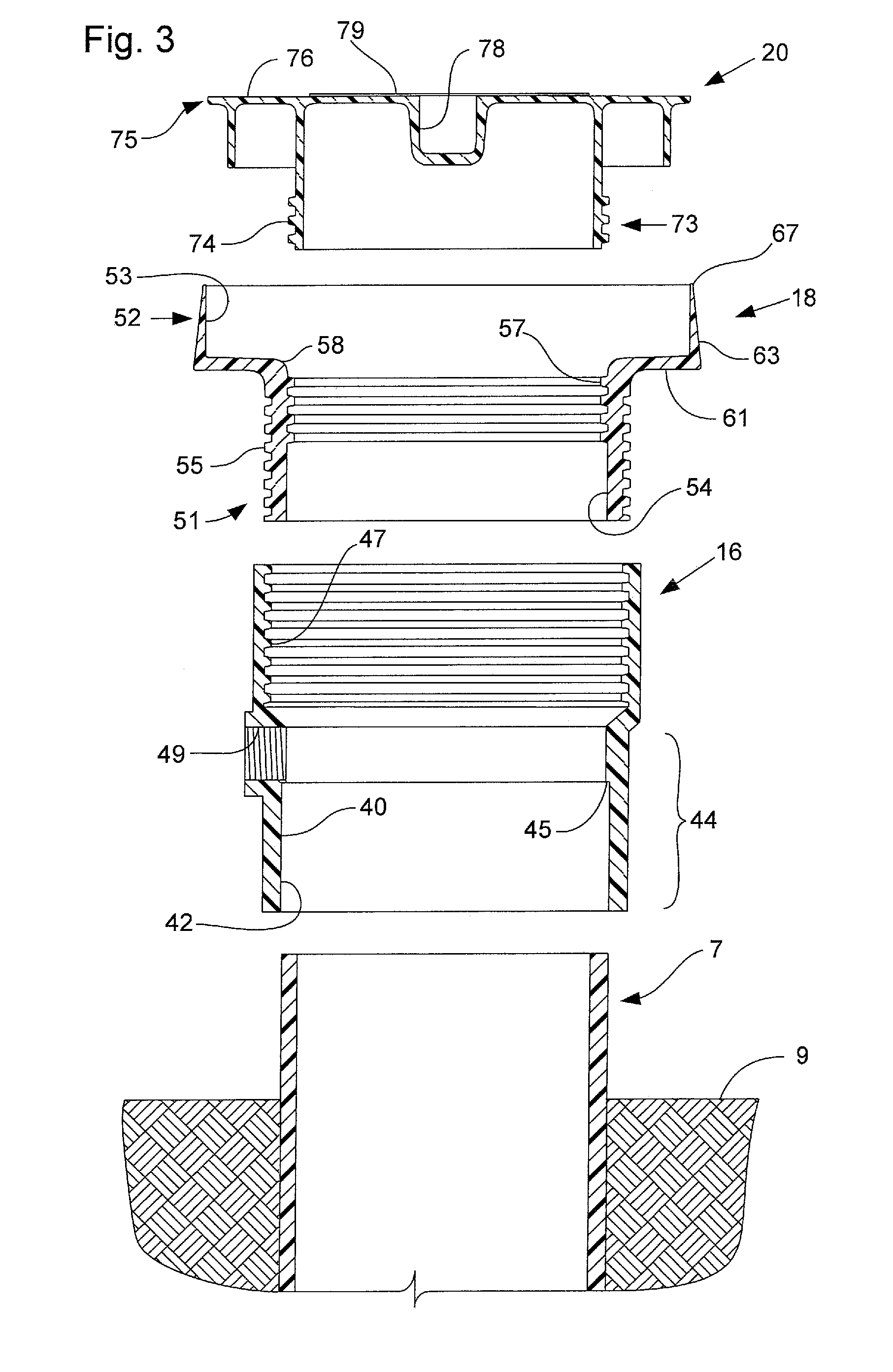
[0042]Referring now to the drawings, and in particular to FIG. 1, there are shown components of an embodiment of a floor drain installation system or rough-in assembly 1 which might more generally be described as a system for conn...


PUM


Abstract

A floor drain installation system includes an adaptor attached to a drain pipe projecting from the ground, a coring sleeve having a bowl-shaped upper end attached to or integral with the adaptor, and a coring plug received within the bowl of the receiver to close off the drain pipe during pouring of a concrete floor and to create a space for subsequent reception of a drain head and grate.

Description

CROSS REFERENCE TO RELATED APPLICATIONS[0001]This application claims priority to U.S. Provisional Application No. 60 / 707,660 filed Aug. 12, 2005 entitled Floor Drain Installation System.BACKGROUND OF THE INVENTION[0002]This invention relates to drains and other utility inlet or outlet type fixtures installed in concrete slabs or floors, and, more particularly, to a system for installing such fixtures using a concrete coring adaptor around which the slab is poured. As used herein, the term fixture is generally intended to include inlet or outlet type utility fixtures such as plumbing drains or drain fixtures, cleanouts, or cleanout fixtures as well as inlets or outlets for electrical conduit or other utility applications.[0003]Drains or drain fixtures are installed in concrete slabs, such as concrete floors in warehouses, garages, basements, parking lots, commercial buildings and residential buildings, to accept water or other liquids from the top surface of the floor and provide a m...

Claims


Application Information

Patent Timeline
Patent Type & Authority Patents(United States)
IPC IPC(8): F16L57/00
CPCE03F5/0407E04G15/061E03F2005/0414E03F2005/0413Y10T137/6988Y10T137/0402
Inventor ISMERT, JOSEPH P.JULIAN, FRANK D.
Owner SIOUX CHIEF MFG
Why Eureka
Try Eureka