Distant measurement method and distant measurement system

a technology of distance measurement and distance measurement, applied in the direction of distance measurement, instruments, surveying and navigation, etc., can solve the problems of changeable noise, affecting the accuracy of distant measurement, and increasing the temperature of the light emitting element, so as to prevent interference between the light beam signal generated by the receiving module of the receiving terminal

Inactive Publication Date: 2010-06-15
ASIA OPTICAL INT LTD
View PDF5 Cites 61 Cited by
  • Summary
  • Abstract
  • Description
  • Claims
  • Application Information

AI Technical Summary

Benefits of technology

[0011]The invention determines the switching sequence by the switching mechanism, thus, operating the emitting module of the emitting terminal and the receiving module of the receiving terminal in accordance with a switching sequence. Thus, interferences between the light beam signals generated by the receiving module of the receiving terminal can be prevented, even if the time interval between the first and second light beam is very short.

Problems solved by technology

However, due to the light emitting element respectively emitting a measurement beam and a reference light beam during the measurement process of the conventional phase-type distant measurement device, temperature of the light emitting element is increased as the number of times of the measuring process is increased, thus, changeable noise occurs.
Further, if the distance between the target and the distant measurement device is fairly short, the time interval between the measurement light beam and the reference light beam received by the light receiving element may be short, thus negatively influencing precision of distant measurement by forming a mutual interference between the measurement light beam and the reference light beam and causing an unpredictable error in the electrical signal output from the light receiving element.

Method used


Image

  • Distant measurement method and distant measurement system
  • Distant measurement method and distant measurement system
  • Distant measurement method and distant measurement system

Examples


Embodiment Construction

[0018]The following description is of the best-contemplated mode of carrying out the invention. This description is made for the purpose of illustrating the general principles of the invention and should not be taken in a limiting sense. The scope of the invention is best determined by reference to the appended claims.

[0019]The embodiment provides a distant measurement method applied by a distant measurement system, thereby assuring precision of the distant measurement system.

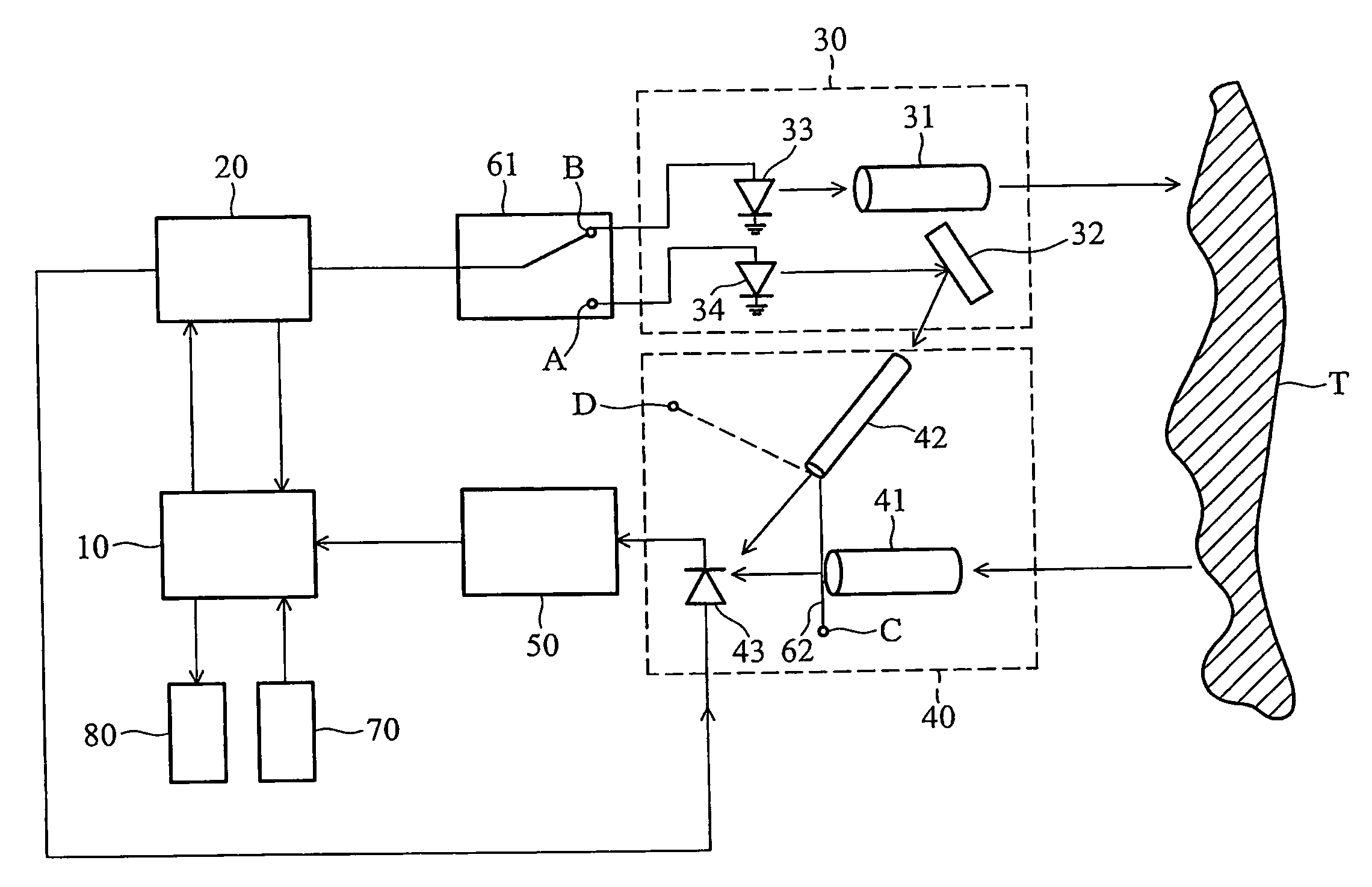
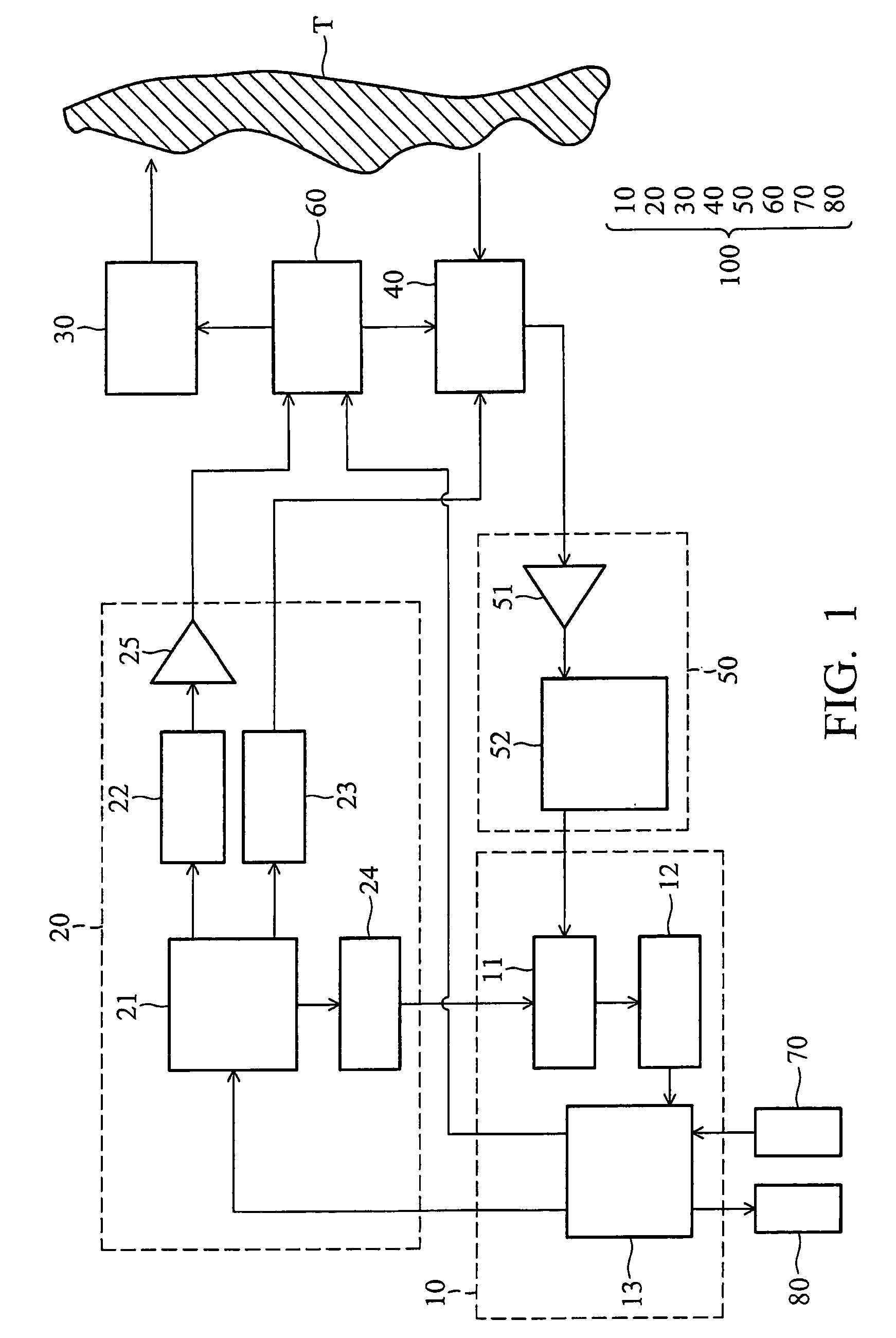
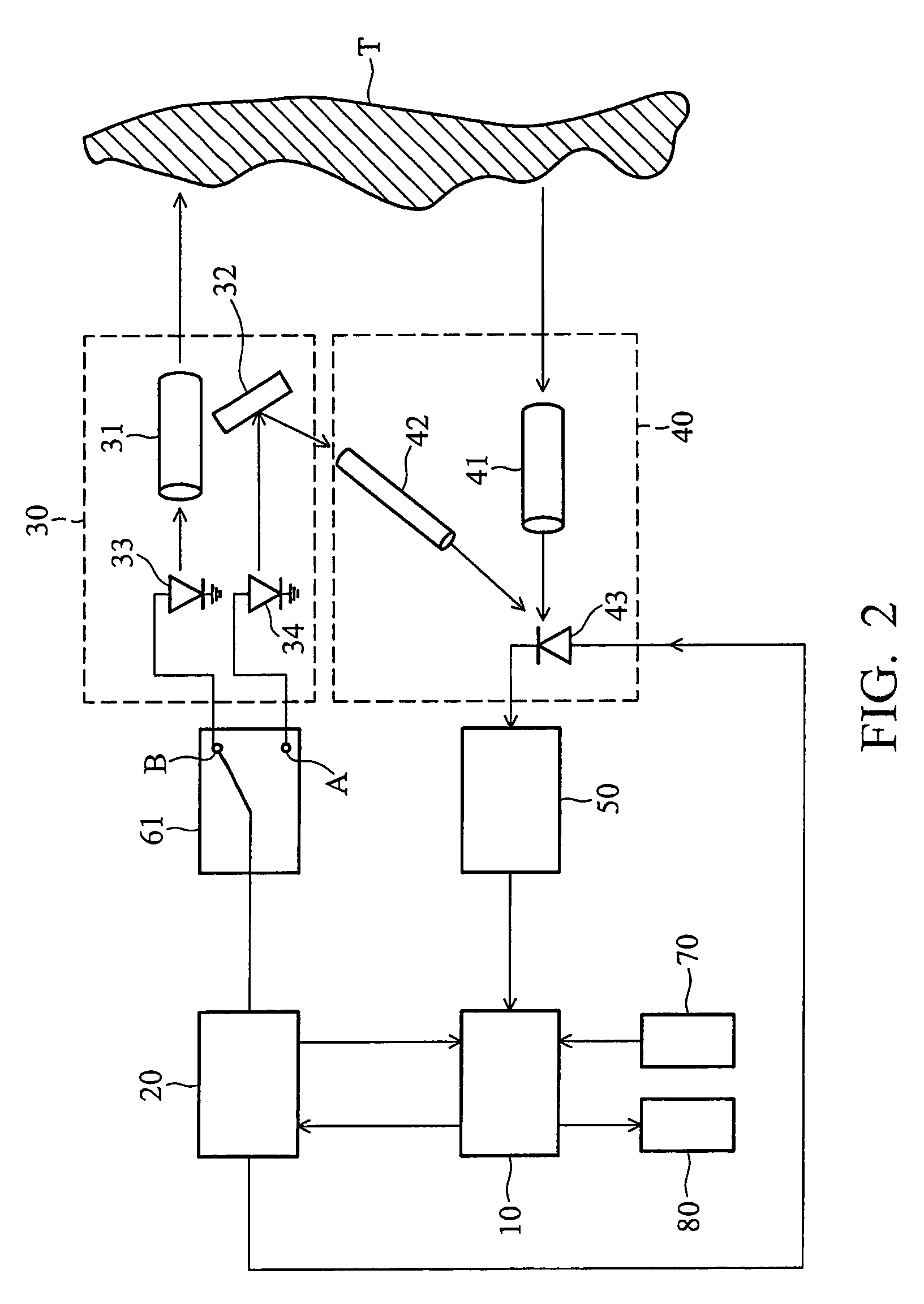
[0020]FIG. 1 is a schematic view of an embodiment of a distant measurement system 100. The distant measurement system 100 at least comprises a controlling module 10, a signal generating module 20, an emitting module 30, a receiving module 40, a processing module 50, a switching unit 60, an inputting module 70 and an outputting module 80.

[0021]The controlling module 10, in accordance with a measuring index coming from the inputting module 70, commands a driving index to the signal generating module 20, thus, com...


PUM


Abstract

A distant measurement method and a distant measurement system are provided. The distant measurement method includes the following steps: emitting a first light beam and a second light beam from an emitting terminal, wherein the first light beam travels toward a target; providing a switching sequence by a switch mechanism; placing a receiving terminal to receive the first light beam reflected from the target in accordance with the switching sequence and correspondingly provide a first electrical signal, and to receive the second light beam and correspondingly provide a second electrical signal; and utilizing a controlling terminal to receive the first and second electrical signals, and calculate distance between the distant measurement system and the target in accordance with a phase differential formed between the first and second electrical signals.

Description

BACKGROUND OF THE INVENTION[0001]1. Field of the Invention[0002]The invention relates to a distant measurement method, and more particularly to a distant measurement method utilizing phase shift variation of light beams to estimate distance and a distant measurement system applied therewith.[0003]2. Description of the Related Art[0004]With the development of electronic techniques and semiconductor laser elements, palm-sized distant measurement devices have been extensively used in the architecture, traffic, graphical reconnaissance and interior decoration fields.[0005]In general, a conventional distant measurement device comprises an emitting module with a built-in light emitting element to emit a light beam and a receiving module with a light receiving element to receive the light beam reflected from a target.[0006]Specifically, the light emitting element and the light receiving element used in a conventional phase-type distant measurement device are made of semiconductor material....

Claims


Application Information

Patent Timeline
Patent Type & Authority Patents(United States)
IPC IPC(8): G01C3/08
CPCG01S17/325G01S17/34
Inventor LUO, YIN-LONGLI, SONGWANG, JUN
Owner ASIA OPTICAL INT LTD
Why Eureka
Try Eureka