
Submersible object with antifouling paint configuration

a technology for submersible objects and anti-fouling substances, which is applied in the direction of coatings, hulls, vessel construction, etc., can solve the problems of affecting the effectiveness of anti-fouling surface, affecting the ability of submersible objects to be properly coated with anti-fouling substances, and affecting the ability of submersible objects to be properly coated

Inactive Publication Date: 2010-06-22
BRUNSWICK CORPORATION
View PDF14 Cites 14 Cited by
  • Summary
  • Abstract
  • Description
  • Claims
  • Application Information

AI Technical Summary

Benefits of technology

The present invention relates to a submersible object that has layers of antifouling materials to prevent the growth of marine organisms on its surface. The first layer is made of a different color than the second layer and can be a paint, while the second layer is an ablative material that contains a chemical to discourage the growth of marine organisms. The substrate can be made of aluminum. The technical effect of this invention is to provide a better protection against marine fouling and to maintain the performance of the submersible object.

Problems solved by technology

When a submersible object, such as a marine drive unit, is provided with an antifouling surface, two problems can occur.
First, during manufacture, it is sometimes very difficult to determine whether or not the entire surface of the submersible object is properly coated with the antifouling substance.
Secondly, after the submersible object is used, it is difficult to determine when the effectiveness of the antifouling surface has decreased sufficiently to require repair or recoating.

Method used


Image

  • Submersible object with antifouling paint configuration
  • Submersible object with antifouling paint configuration
  • Submersible object with antifouling paint configuration

Examples


Embodiment Construction

[0023]Throughout the description of the preferred embodiment of the present invention, like components will be identified by like reference numerals.

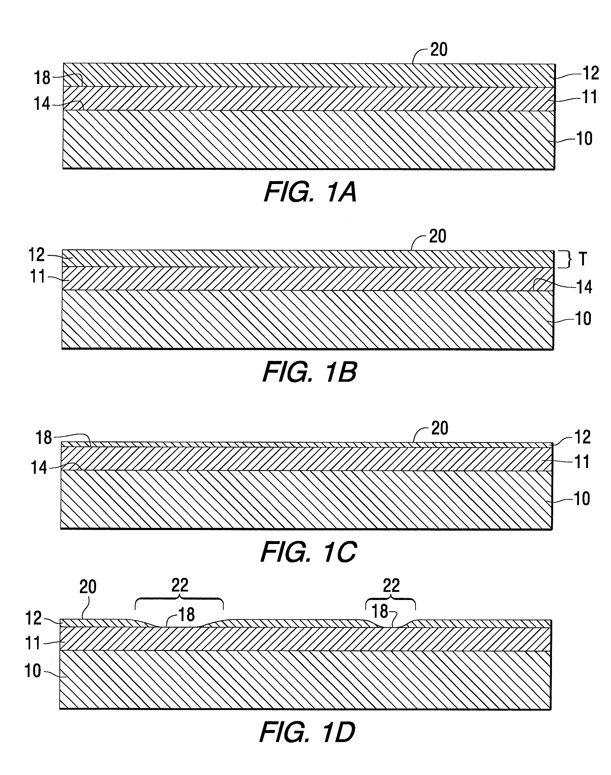
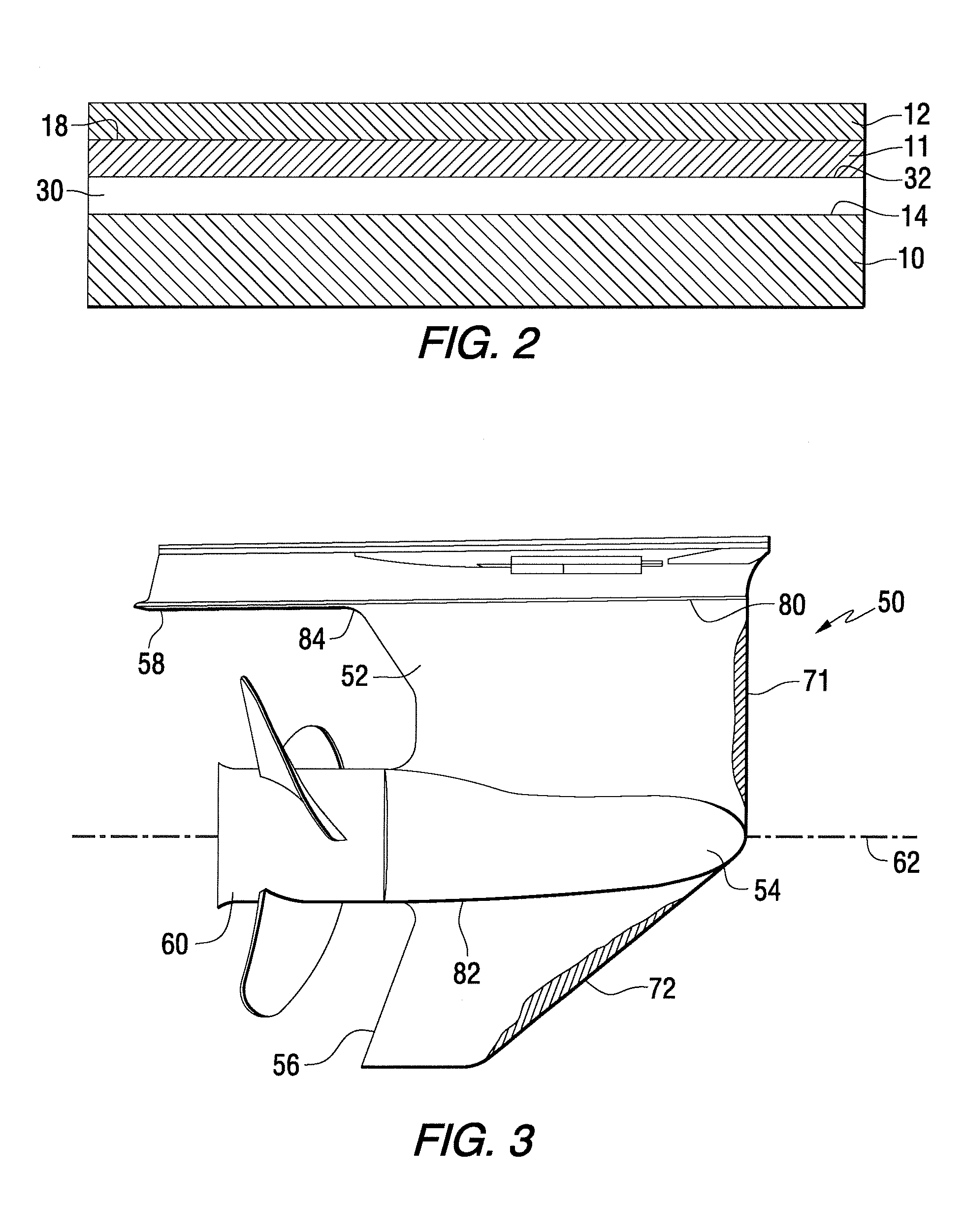
[0024]FIG. 1A is a simplified schematic view of a section of the submersible object made in accordance with a preferred embodiment of the present invention. It should be understood that FIGS. 1A-1B are enlarged section views drawn without regard to scale so that the various layers, or coatings, of antifouling paint can be more easily identified and clearly described. In FIG. 1A, a substrate 10 is shown with a first layer 11 of a first antifouling material disposed on a surface 14 of the substrate 10. A second layer 12 of a second antifouling material is disposed on the first layer 11. More precisely, the second layer 12 is disposed on an outer surface 18 of the first layer 11. The first and second layers, 11 and 12, are visually distinct from each other. In a particularly preferred embodiment of the present invention, the first layer 11...


PUM

PropertyMeasurementUnit
period of timeaaaaaaaaaa
antifoulingaaaaaaaaaa
timeaaaaaaaaaa

Abstract

Antifouling materials are used to provide first and second layers or coatings on a submersible object. The first and second layers are visually distinct from each other, such as being made of two distinct colors, so that the ablation of an outer layer will be evident when an inner layer is exposed to show a different color in the regions of ablation. The materials for the first and second layers can be chemically active to cause the antifouling nature of the materials or can be electrically conductive to permit their use in the creation of either chlorine bubbles on the wetted surface or a change in ionic characteristic of water in contact with the wetted surface.

Description

BACKGROUND OF THE INVENTION[0001]1. Field of the Invention[0002]The present invention is generally related to a submersible object, such as a marine drive unit, and, more particularly, to a configuration of layers of an antifouling substance which is applied in two steps to provide an indicative arrangement of visually distinct appearances that facilitate the detection of missing portions of an outer layer.[0003]2. Description of the Related Art[0004]Those skilled in the art of marine propulsion systems are aware of many different methods for discouraging the growth of marine organisms on surfaces of boats, marine drives, and other submerged devices such as grates and pipes used to conduct the flow of liquids below the surface of a body of water. Some systems use electrically energized surfaces to induce the creation of chlorine bubbles in sea water applications or induce changes in the ionic characteristics of water near surfaces in fresh water applications. In addition, many diffe...

Claims


Application Information

Patent Timeline
Patent Type & Authority Patents(United States)
IPC IPC(8): B63B59/00
CPCC09D5/1693B63B59/04
Inventor ANDERSON, KEVIN R.MISORSKI, CHRISTOPHER J.
Owner BRUNSWICK CORPORATION
Learn More