
Railing assembly with detachable and upgradeable components

a railing assembly and hollow component technology, applied in the field of outdoor railing systems, can solve the problems of not being desirable in every case, closed tubular rails with routed openings have certain limitations that may affect whether or not they can be used in a given project, and cannot meet the minimum load requirements

Active Publication Date: 2010-06-29
BARRETTE OUTDOOR LIVING INC
View PDF13 Cites 44 Cited by
  • Summary
  • Abstract
  • Description
  • Claims
  • Application Information

AI Technical Summary

Benefits of technology

The invention is a railing system that includes an upper core member and a lower core member with a base connector and a cap connector. The system also includes a cap member and a base member that enclose the upper core member. The invention also includes a kit for fabricating a railing span with balusters at a selected spacing. Additionally, the invention includes a method for routing an opening for a baluster in an inclined railing structure. The technical effects of the invention include improved stability, durability, and flexibility of the railing system, as well as simplified installation and adjustability of the baluster position.

Problems solved by technology

There are certain drawbacks in using closed tubular rails in a railing system.
Load bearing rails that fail to meet the minimum load requirements can not be used for residential construction.
Therefore, closed tubular rails with routed openings have certain limitations that may affect whether or not they can be used in a given project.
Although aluminum stiffeners increase structural integrity, they may not be desirable in every case.
Compared to plastic material, aluminum stiffeners are relatively difficult to cut to a specified length.
Closed tubular rails also limit the ability to run wires, cables and utility lines along the railing structure.
This leaves the wiring visible on the exterior of the railing, which can detract from the appearance of the railing.
In addition, the size and shape of the railing may not allow for more than a few wires to be run along the railing.
The process of feeding wiring through a closed tubular rail may be further complicated by posts or other components that divide sections of rail and obstruct the hollow interior of the closed rails.
Therefore, the process of cutting into an installed railing can require significant time and labor.
Cutting through the sides of plastic rails also leaves holes that may detract from the appearance of the railing system.
In contrast, many known systems that are designed to conceal hardware require the handling of more components, which increase the time and expense for installing the railing assembly.
Unfortunately, routed openings can create fracture zones that compromise the structural integrity of the railing system.

Method used


Image

  • Railing assembly with detachable and upgradeable components
  • Railing assembly with detachable and upgradeable components
  • Railing assembly with detachable and upgradeable components

Examples


Embodiment Construction

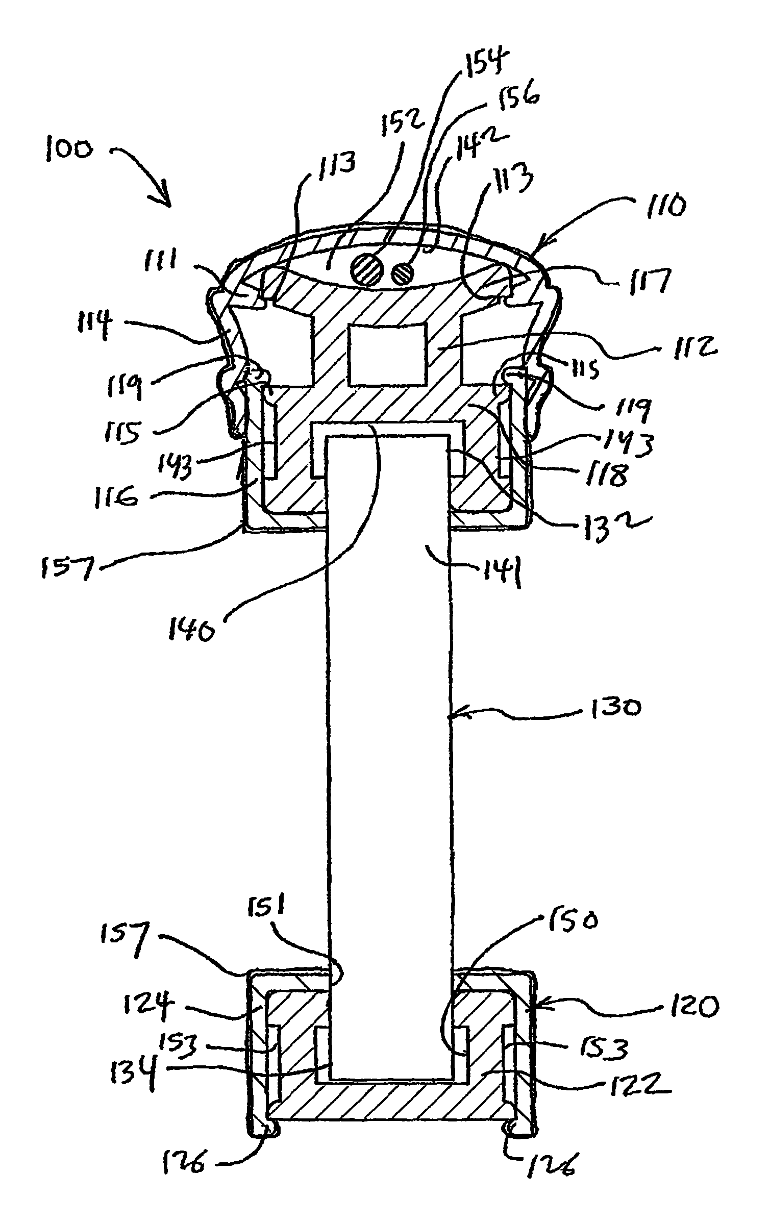
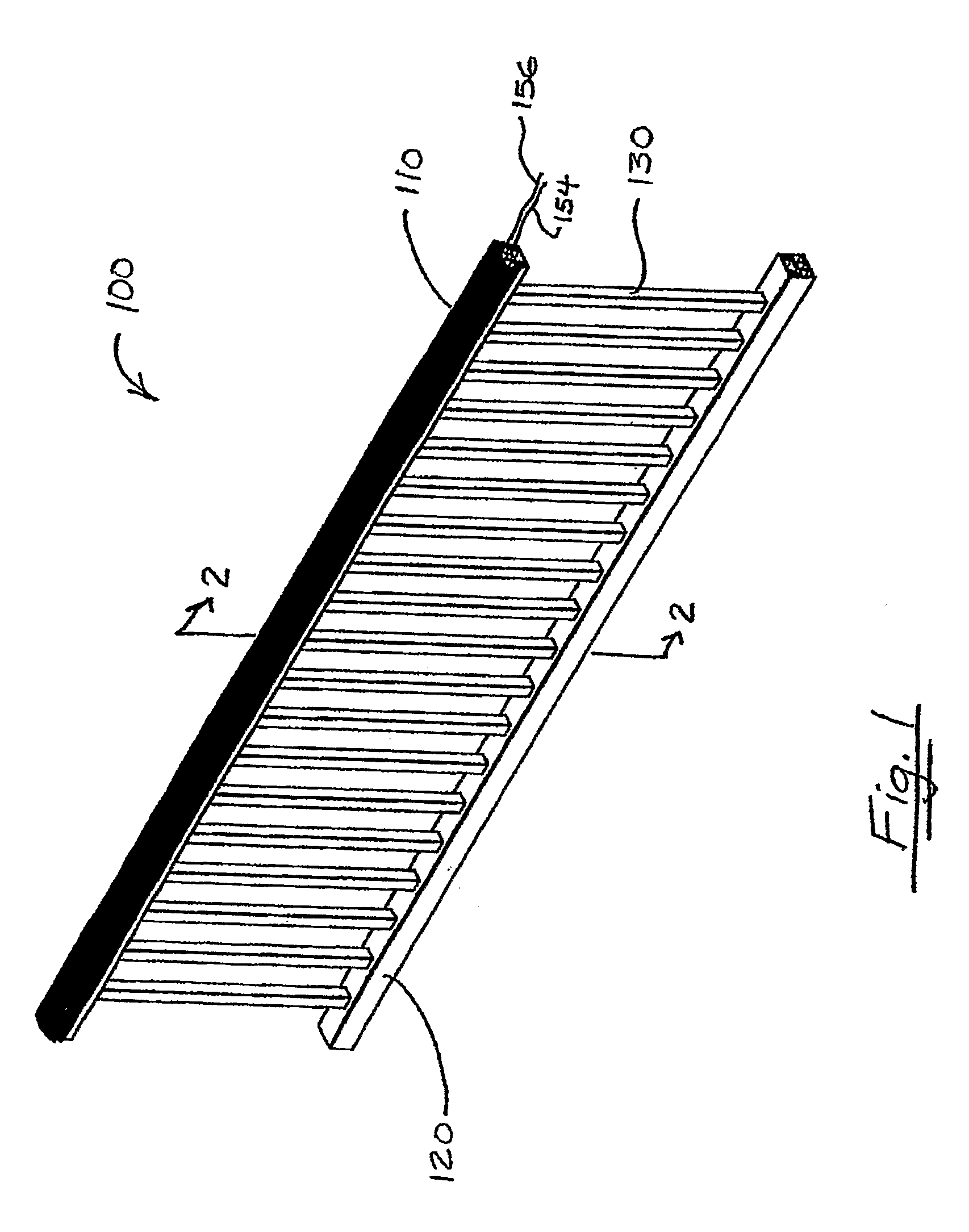
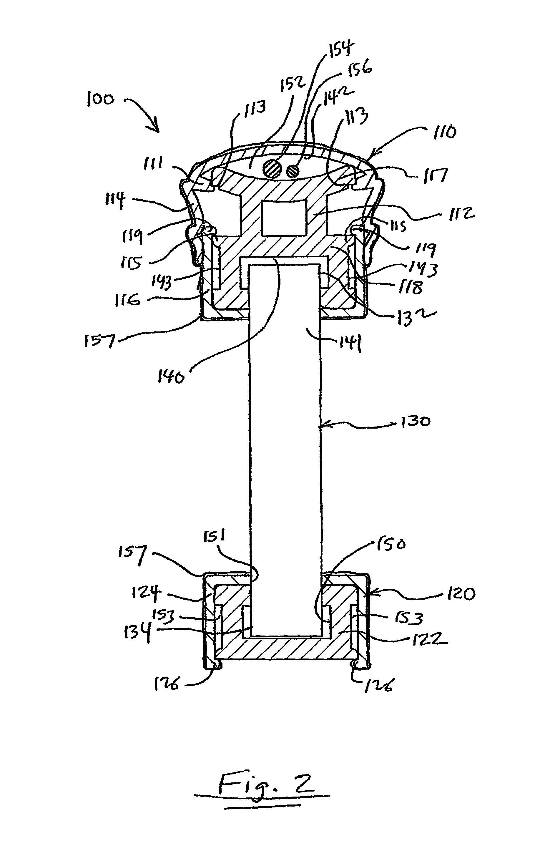
[0070]The drawbacks associated with closed tubular railing assemblies are addressed to a great degree by a railing system in accordance with the present invention, which features structural core members having detachable cover elements. The detachable cover elements permit access to the interior of the assembly without cutting into the assembly or dismantling rails from the support structure. Therefore, cover elements can be detached, for instance, to run utility wiring through the railing system. In addition, the detachable cover elements allow for design flexibility, so that the owner can incorporate different decorative components into the railing system, change decorative components as desired, and replace damaged components, without disassembling or modifying the structural components that support the railing.

[0071]Referring now to the drawing figures in general, and to FIG. 1 specifically, a railing span 100 is shown. The span 100 includes an upper rail 110 and a lower rail 12...


PUM


Abstract

A railing system includes an upper core member having a cap connector. In a first embodiment, a railing system includes a cap member having a cap flange that detachably couples with the cap connector on the upper core member. The cap member forms an enclosed conduit between the cap member and the upper core member. In a second embodiment, a kit for fabricating a railing span is contained in a packaging. The kit includes an upper core member and lower core member having selected lengths and a plurality of balusters for connection between the upper and lower core members. In a third aspect of the invention, a method of routing an opening for a baluster used in an inclined railing structure includes the step of plunging a router bit into a side of a component at an angle based on the installed angle of the inclined railing structure.

Description

RELATED APPLICATIONS[0001]This application is a U.S. National Phase Application of PCT International Application PCT / US2006 / 016735, filed May 1, 2006, the contents of which are incorporated by reference. This application claims the benefit of U.S. Provisional Application No. 60 / 757,739, filed Jan. 10, 2006, and further claims the benefit of U.S. Provisional Application No. 60 / 677,285, filed May 3, 2005, the contents of both applications being incorporated by reference herein.FIELD OF THE INVENTION[0002]The present invention relates to outdoor railing systems, and particularly to outdoor railing assemblies having detachable hollow components to permit installation and servicing of cable, wiring and utility lines through the railing system after the railing system is installed.BACKGROUND[0003]Outdoor railing structures, such as handrails for decks and terraces, are constructed of a variety materials. Many manufacturers and builders of railing structures use polyvinylchloride (PVC) and...

Claims


Application Information

Patent Timeline
Patent Type & Authority Patents(United States)
IPC IPC(8): E04H17/14
CPCE04F11/181E04F11/1842H02G3/0456E04F2011/1897E04F2011/1868E04F2011/1827E04F2011/1819E04F11/1853E04F2011/1821E04F11/1844
Inventor TERRELS, CHRISTOPHER J.SCHNEIDER, CHRISTOPHER MICHAEL
Owner BARRETTE OUTDOOR LIVING INC
Learn More