Knee airbag device for vehicle

a technology for airbag devices and vehicles, which is applied to vehicle components, pedestrian/occupant safety arrangements, vehicular safety arrangements, etc., can solve the problems of widening the distance between the knees and difficulty in deploying the knee airbag, and achieves the effect of smooth deployment of the knee airbag

Inactive Publication Date: 2010-06-29
TOYOTA JIDOSHA KK
View PDF33 Cites 5 Cited by
  • Summary
  • Abstract
  • Description
  • Claims
  • Application Information

AI Technical Summary

Benefits of technology

[0011]According to the above-described aspect, when the gas is supplied into the knee airbag stored in the folded state at the predetermined position in the vehicle, the knee airbag is inflated and deployed toward the area below the steering column so that the knee airbag is disposed between the knees of the occupant and the lower portion of the instrument panel. As a result, the knees of the occupant is protected.
[0012]In the above-described embodiment, the thickness regulation member is provided in the knee airbag at the position in the contact portion that contacts each of the knees of the occupant. Therefore, the thickness of the knee airbag at the position in the contact portion is smaller than the thickness of the knee airbag at the portion other than the contact portion. Thus, it is possible to smoothly deploy the knee airbag even when the occupant is small, and the gap between the knees of the occupant and the lower portion of the instrument panel is narrow.
[0015]According to the above-described aspect, the knee airbag further includes the instrument panel-side foundation cloth positioned close to the instrument panel, and the occupant-side foundation cloth positioned close to the occupant. The thickness regulation member is the pinched portion formed by sewing together the instrument panel-side foundation cloth and the occupant-side foundation cloth at the position in the contact portion, when the instrument panel-side foundation cloth and the occupant-side foundation cloth are sewn together at the peripheral portion. Therefore, it is possible to easily make the thickness of the knee airbag small only at the position in the contact portion that contacts each of the knees of the occupant, without increasing the number of components. Also, because the number of components is not increased, the knee airbag in the folded state does not take up much space.
[0017]According to the above-described aspect, the knee airbag further includes the instrument panel-side foundation cloth positioned close to the instrument panel, and the occupant-side foundation cloth positioned close to the occupant. The thickness regulation member is the connection member made of cloth, which connects the instrument panel-side foundation cloth and the occupant-side foundation cloth in a direction of the thickness of the knee airbag, and which restricts the thickness of the knee airbag at the position in the contact portion. Therefore, the width of the connection member made of cloth can be set to any value although the number of components is increased. Accordingly, when the thickness of the knee airbag is made small at the position in the contact portion, it is possible to easily adjust the thickness of the knee airbag at the position in the contact portion, for example, to approximately a half of, or a third of the thickness of the knee airbag at the general portion (i.e., the portion other than the contact portion).
[0019]According to the above-described aspect, the knee airbag further includes the instrument panel-side foundation cloth positioned close to the instrument panel, and the occupant-side foundation cloth positioned close to the occupant. The thickness regulation member is the indentation which is formed in the peripheral portion of the knee airbag at the position in the contact portion, and which is indented toward the inside of the knee airbag, wherein the peripheral portion of the knee airbag is formed by joining the instrument panel-side foundation cloth and the occupant-side foundation cloth at each periphery of the instrument panel-side foundation cloth and the occupant-side foundation cloth. The indentation is formed by sewing together the instrument panel-side foundation cloth and the occupant-side foundation cloth, each of which has a shape indented toward the inside of the knee airbag at the position in the contact portion. Therefore, it is possible to easily make the thickness of the knee airbag small only at the position in the contact portion that contacts each of the knees of the occupant, without increasing the number of components. Also, because the number of components is not increased, the knee airbag in the folded state does not take up much space. Further, because the shape of each of the instrument panel-side foundation cloth and the occupant-side foundation cloth is changed, only the process of sewing the instrument panel-side foundation cloth and the occupant-side foundation cloth together at the peripheral portion is required. That is, for example, the process of forming pinched portion in the knee airbag at the position in the contact portion that contacts each of the knees of the occupant is not required. Therefore, the instrument panel-side foundation cloth and the occupant-side foundation cloth are easily sewn together.

Problems solved by technology

Therefore, a gap between the knees and the instrument panel is narrow, and thus, it is difficult to deploy the knee airbag.
Also, when the knees are positioned close to the instrument panel, the knee airbag may enter an area between the knees, and may widen the distance between the knees.

Method used


Image

  • Knee airbag device for vehicle
  • Knee airbag device for vehicle
  • Knee airbag device for vehicle

Examples


first embodiment

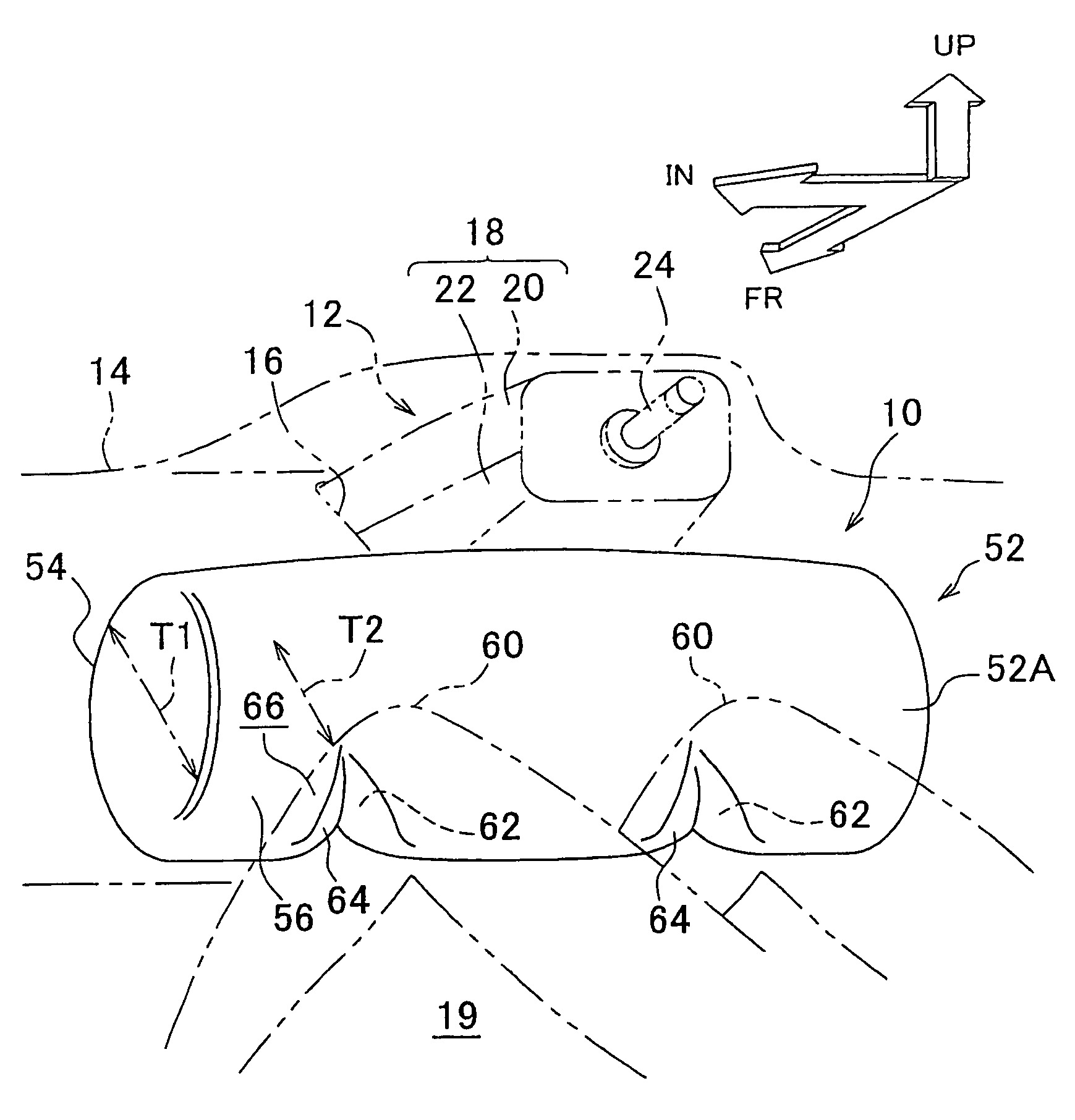
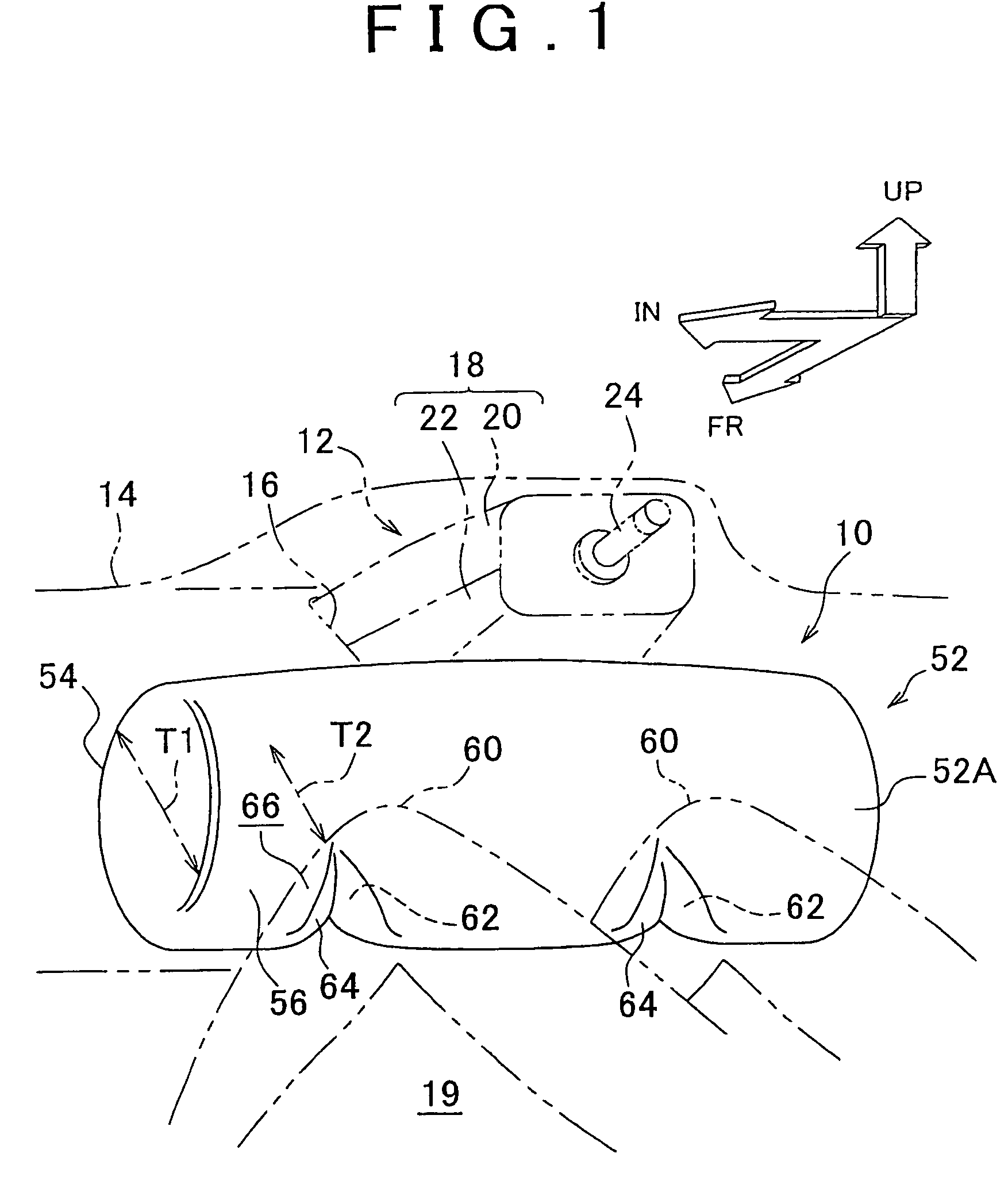
[0032]Hereinafter, a knee airbag device for a vehicle according to a first embodiment of the invention will be described with reference to FIG. 1 to FIG. 3. In FIG. 1, the arrow FR indicates the front of a vehicle. The arrow UP indicates the top of the vehicle. The arrow IN indicates the inside of the vehicle in a vehicle-width direction.

[0033]FIG. 1 is a perspective view showing a knee airbag device according to an embodiment, which is operated, and which is viewed from the rear of the vehicle. FIG. 2 is a lateral view showing the knee airbag device that is operated. FIG. 3A is a plan view showing the configuration of a knee airbag according to the first embodiment. FIG. 3B is a cross sectional view of the main portion of the knee airbag that is inflated and deployed.

[0034]As shown in FIG. 1 to FIGS. 3A and 3B, the knee airbag device 10 is disposed under the rear end of the steering column 12. That is, an opening portion 16 is formed on a portion of the instrument panel 14, which f...

second embodiment

[0048]Hereinafter, a knee airbag device for a vehicle according to a second embodiment of the invention will be described with reference to FIGS. 4A to 4C. The same and corresponding portions as those in the first embodiment will be denoted with the same reference numerals, and the description thereof will be omitted.

[0049]As shown in FIGS. 4A to 4C, in the second embodiment, a knee airbag 70 includes an instrument panel-side foundation cloth 54 and an occupant-side foundation cloth 56. Straps 62 are provided inside the knee airbag 70 at positions in contact portions that contact the knees 60. Each strap 62 has an angular U-shape cross section. The straps 70 may be regarded as the thickness regulation member and the connection member. One side portion 72A of each strap 72 is sewn to the instrument panel-side foundation cloth 54 and the other side portion 72B is sewn to the occupant-side foundation cloth 56. The thickness of the inflated and deployed knee airbag 70 at the positions i...

third embodiment

[0053]Hereinafter, a knee airbag device for a vehicle according to a third embodiment of the invention will be described with reference to FIGS. 5A and 5B. The same and corresponding portions as those in the first embodiment will be denoted with the same reference numerals, and the description thereof will be omitted.

[0054]As shown in FIGS. 5A and 5B, in the third embodiment, a knee airbag 80 includes an instrument panel-side foundation cloth 82 and an occupant-side foundation cloth 84, as in the first embodiment and the second embodiment. In addition, in the third embodiment, each of the instrument panel-side foundation cloth 82 and the occupant-side foundation cloth 84 is formed by cutting cloth so that each of the instrument panel-side foundation cloth 82 and the occupant-side foundation cloth 84 has a shape indented toward the inside of the knee airbag 80 at positions in the contact portions. The instrument panel-side foundation cloth 82 and the occupant-side foundation cloth 84...


PUM


Abstract

A knee airbag device for a vehicle includes a gas generation portion that is operated to generate gas; a knee airbag that is disposed in a folded state at a predetermined position in a vehicle, wherein when the knee airbag receives the gas, the knee airbag is inflated and deployed toward an area below a steering column so that the knee airbag is disposed between knees of an occupant and a lower portion of an instrument panel; and a thickness regulation member that is provided in the knee airbag at a position in a contact portion that contacts each of the knees of the occupant, and that regulates the thickness of the knee airbag such that the thickness of the knee airbag at the position in the contact portion is smaller than the thickness of the knee airbag in a portion other than the contact portion.

Description

INCORPORATION BY REFERENCE[0001]The disclosure of Japanese Patent Application No. 2006-301672 filed on Nov. 7, 2006 including the specification, drawings and abstract is incorporated herein by reference in its entirety.BACKGROUND OF THE INVENTION[0002]1. Field of the Invention[0003]The invention relates to a knee airbag device for a vehicle, which includes a knee airbag that is inflated and deployed to restrain the knees of an occupant when a frontal collision occurs.[0004]2. Description of the Related Art[0005]Various knee airbag devices for a vehicle have been proposed to protect the knees of an occupant. For example, each of International Patent Publication WO2002 / 004262, and Japanese Patent Application Publication No. 9-104317 describes a knee airbag device that includes an airbag module disposed inside a column cover for a steering column.[0006]However, in the knee airbag device described in each of the above publications, because a knee airbag, which is inflated and deployed t...

Claims


Application Information

Patent Timeline
Patent Type & Authority Patents(United States)
IPC IPC(8): B60R21/231B62D1/16B60R21/20B60R21/203B60R21/2334B60R21/2338
CPCB60R21/231B60R21/2338B60R2021/23382B60R2021/23316B60R2021/23169
Inventor FUKAWATASE, OSAMUMORO, TOMOYUKIIMAMURA, KENJISANADA, AKIYOSHI
Owner TOYOTA JIDOSHA KK
Why Eureka
Try Eureka