
Apparatus including igniter assembly

a technology of an igniter and an accessory body, which is applied in the direction of vehicle components, pedestrian/occupant safety arrangements, weapons, etc., can solve the problems of increasing the gap and increasing the cost of components

Active Publication Date: 2010-06-29
DAICEL CHEM IND LTD
View PDF19 Cites 12 Cited by
  • Summary
  • Abstract
  • Description
  • Claims
  • Application Information

AI Technical Summary

Benefits of technology

The present invention relates to an apparatus with an igniter assembly. The assembly includes an igniter main body with an ignition portion and an electroconductive pin, surrounded by a resin portion. The assembly is fixed to the housing by an igniter collar that engages with a concave portion in the resin portion. The invention also includes a method of assembling the apparatus with the igniter assembly. The technical effects of the invention include improved ignition reliability and stability, as well as simplified assembly and disassembly processes.

Problems solved by technology

Where a small gap is formed between the igniter collar and resin due to shrinkage of resin during cooling after injection, moisture penetrates into the gap, causing corrosion and increasing the gap.
Therefore, a portion of the collar that comes into contact with the resin has to be subjected to anticorrosive treatment, which rises cost of components.

Method used


Image

  • Apparatus including igniter assembly
  • Apparatus including igniter assembly
  • Apparatus including igniter assembly

Examples


embodiments of invention

(1) Gas Generator of FIG. 1 and Method for Assembling the Same

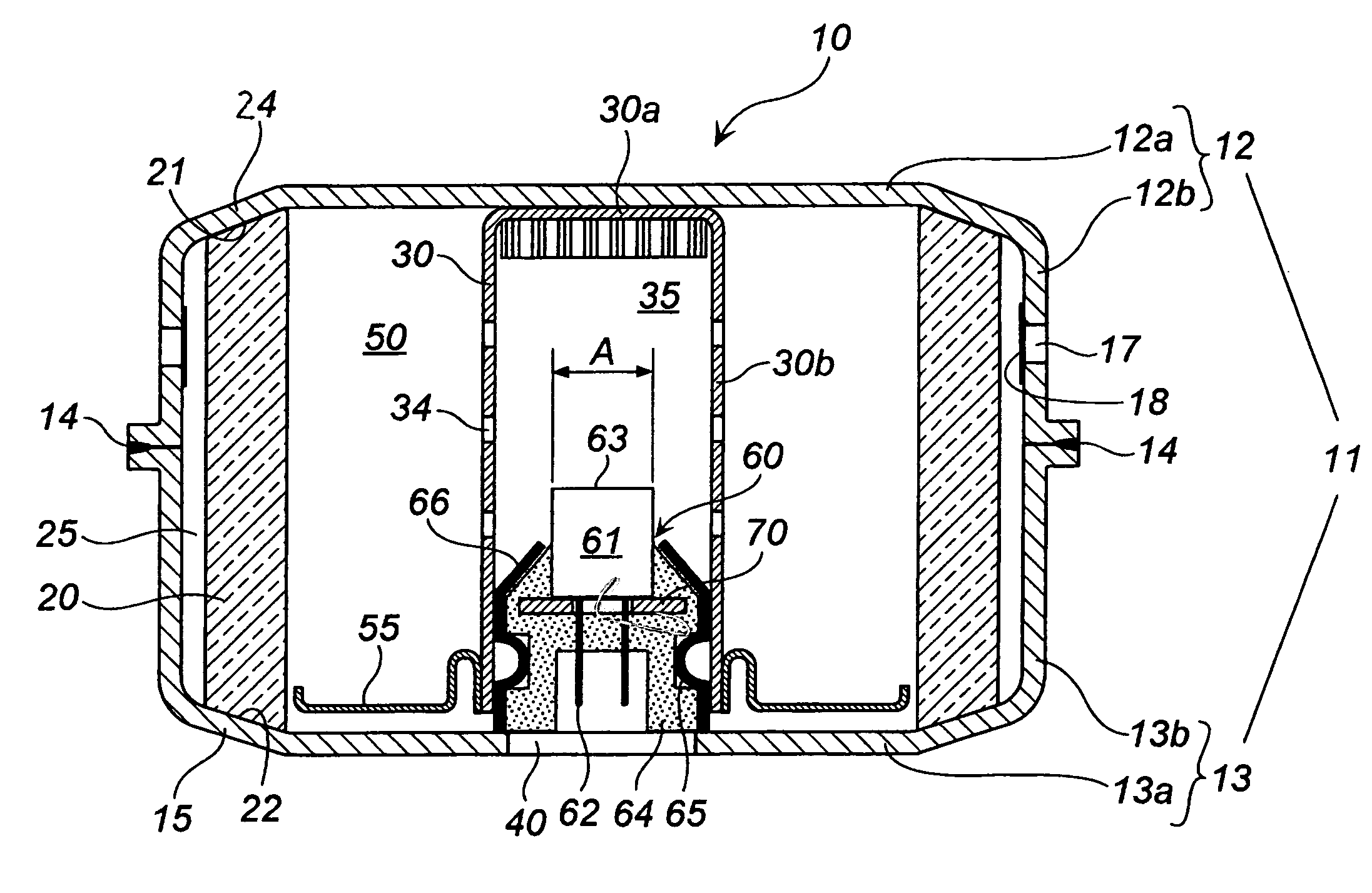
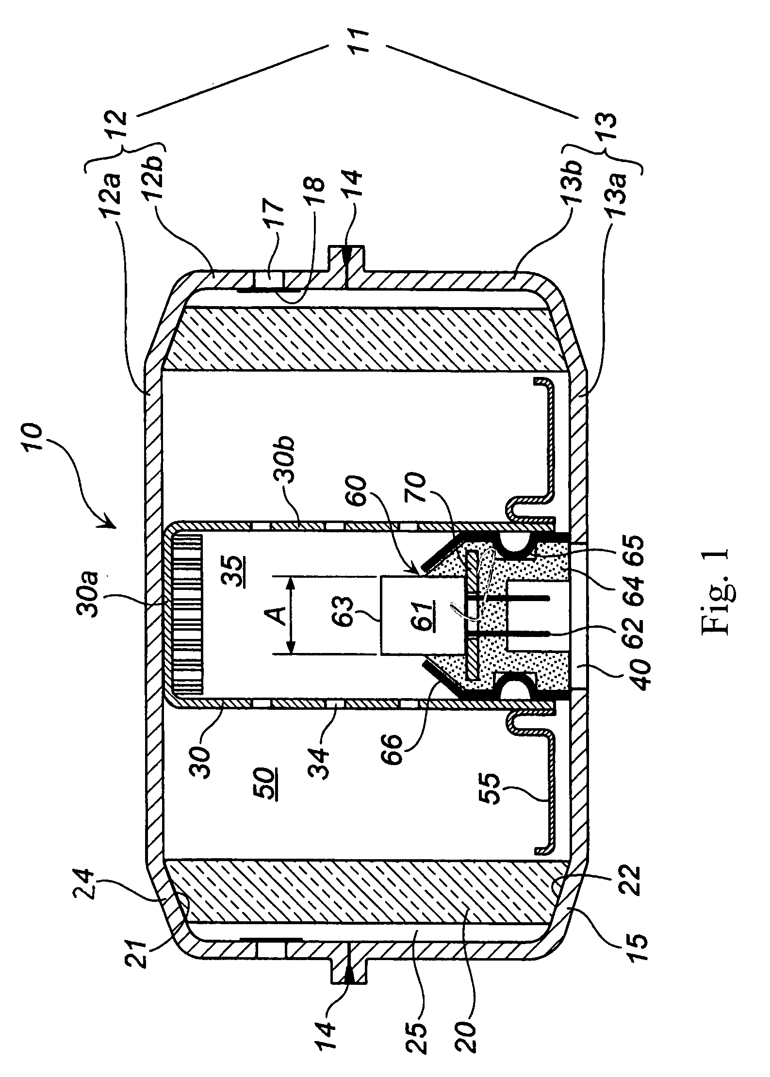
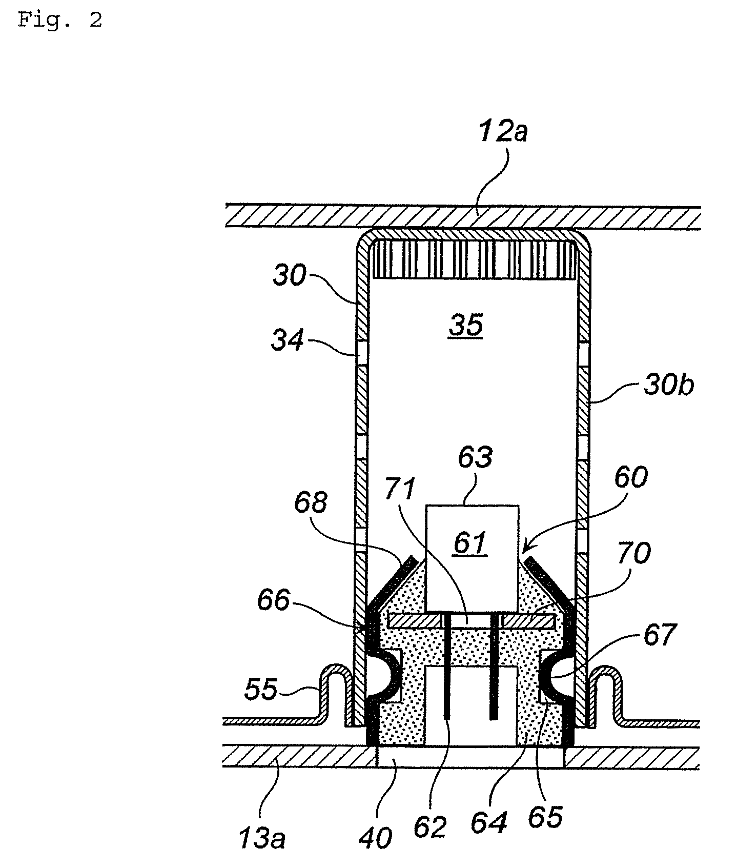
[0069]An example of applying the present invention to a gas generator for a restraining device of a vehicle will be described below. FIG. 1 is a vertical cross-sectional view of the gas generator. FIG. 2 is a partial enlarged view of FIG. 1.

[0070]In a gas generator 10, an outer shell container is formed by a housing 11 obtained by joining a diffuser shell 12 forming a top plate 12a and a circumferential wall 12b and a closure shell 13 forming a bottom plate 13a and a remaining circumferential wall 13b.

[0071]The diffuser shell 12 and closer shell 13 are joined by laser welding or the like in a welding portion 14, this welding forming a single circumferential wall (combination of the circumferential walls 12b and 13b).

[0072]An upper annular inclined surface 24 is provided in an annular contact portion between the top plate 12a and circumferential wall portion 12b of the diffuser shell 12, and a lower annular inclined surfa...


PUM


Abstract

The present invention provides an apparatus provided with an igniter assembly including: an igniter main body having an ignition portion, provided with an ignition agent, and an electroconductive pin, a resin portion surrounding at least part of the igniter main body and a substantially cylindrical igniter collar fixed to an outer surface of the resin portion, the igniter assembly being disposed in an opening formed in a bottom portion of a housing, the igniter collar of the igniter assembly being fixed to the housing, the igniter collar fixing to the resin portion y deforming the igniter collar so as to engage the igniter collar with a concave portion in the resin portion.

Description

[0001]This nonprovisional application claims priority under 35 U.S.C. §119(a) on Patent Application No. 2006-239916 filed in Japan on 5 Sep. 2006, and 35 U.S.C. §119(e) on U.S. Provisional Application No. 60 / 825,042 filed on 8 Sep. 2006, which are incorporated by reference.BACKGROUND OF INVENTION[0002]1. Field of Invention[0003]The present invention relates to an apparatus including an igniter assembly suitable as an inflator for use in a restraining system of a vehicle.[0004]2. Description of Related Art[0005]An igniter assembly is known in which an igniter main body is integrated with a metal collar by a resin, this igniter main body including an ignition agent, a bridge wire for igniting the ignition agent, and electroconductive pins for supplying an electric current for heating the bridge wire.[0006]Where a small gap is formed between the igniter collar and resin due to shrinkage of resin during cooling after injection, moisture penetrates into the gap, causing corrosion and inc...

Claims


Application Information

Patent Timeline
Patent Type & Authority Patents(United States)
IPC IPC(8): B60R21/26B60R21/264
CPCF42B3/198F42B3/103
Inventor YAMAZAKI, MASAYUKI
Owner DAICEL CHEM IND LTD
Learn More