Powered shoe tightening with lace cord guiding system

a technology of guiding system and shoe lace cord, which is applied in the direction of shoe lace fastening, haberdashery, clothing, etc., can solve the problems of wearer trip, difficulty in effective manual tie-up of shoe lace cord, inconsistent and fast, etc., and achieve the effect of fast and convenient method

Inactive Publication Date: 2010-07-13
USSHER TIM JAMES
View PDF6 Cites 261 Cited by
  • Summary
  • Abstract
  • Description
  • Claims
  • Application Information

AI Technical Summary

Benefits of technology

[0004]To overcome these problems this power lace invention allows people to tighten and loosen the single lace cord running inside smooth gliding tubes woven into the upper part of the shoe's tongue and round lace plate loops on the shoe's uppers, by pressing a button on their shoe activating a small battery powered motor winder in the heel, which winds in the cord and is held at the desired tension with a clasp through which the cord runs and can be manually released, allowing for a fast and convenient method for all people to have the properties of traditional lace fitted shoes without having to tie a bow / knot.

Problems solved by technology

Traditional tie up shoe lace cords can be difficult to manually tie effectively, consistently and quickly.
Furthermore lace bows / loops being positioned on the outside of the shoe can come undone or catch on something potentially causing the wearer to trip.

Method used


Image

  • Powered shoe tightening with lace cord guiding system
  • Powered shoe tightening with lace cord guiding system
  • Powered shoe tightening with lace cord guiding system

Examples


Embodiment Construction

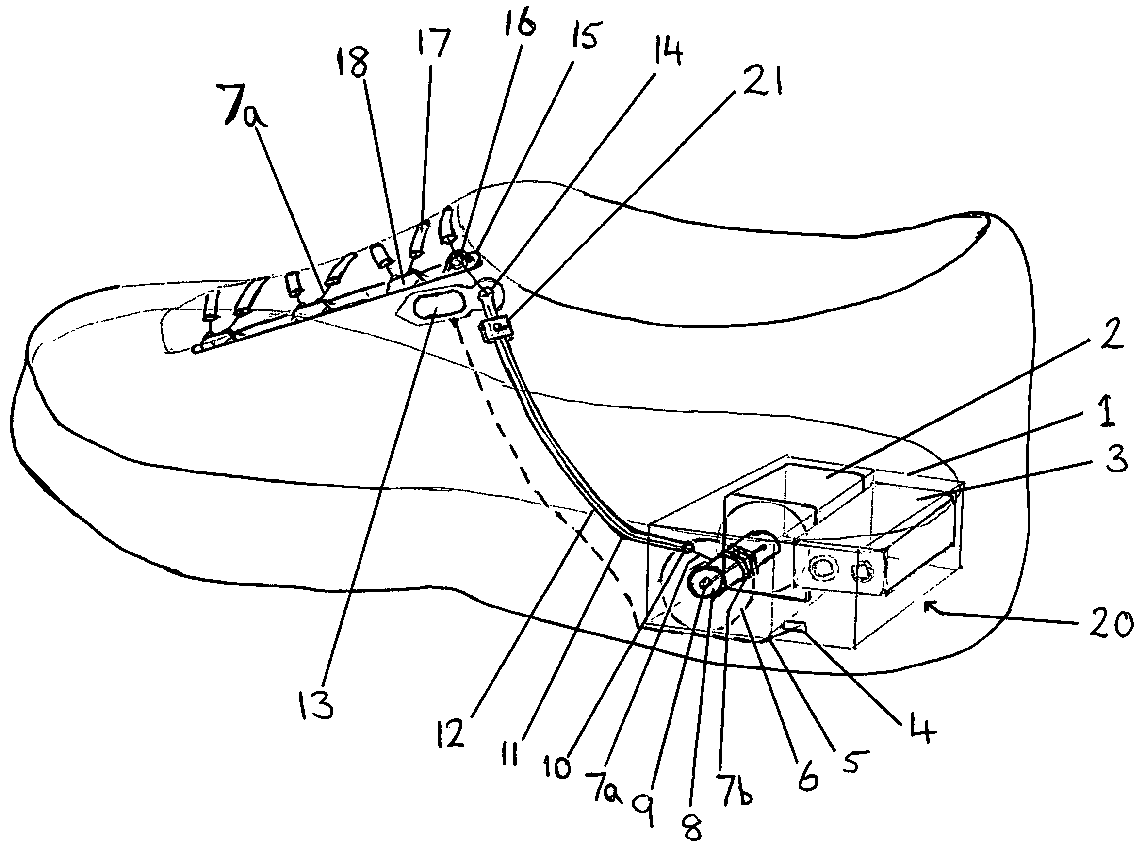
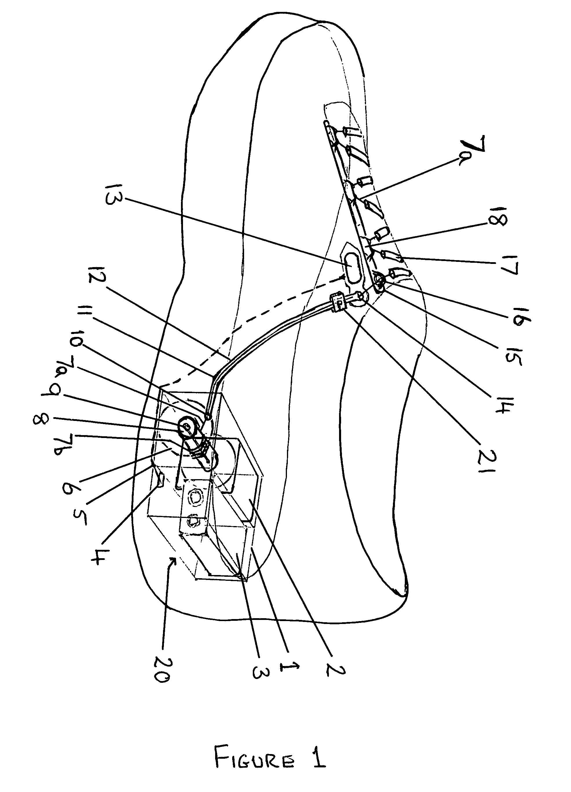
[0010]An example of the power lace invention will now be described by referring to the accompanying drawings;

[0011]The single housing case 1 for both the motor 2 and the battery 3 is fixed within a recess in the shoe's heel and covered with a detachable plate or lid 20 likely to be in the style of the rest of the shoe's sole and removable for access to the motor 2 and battery 3. The motor 2 and battery 3 are held firmly in place with their fit into the housing box 1 so as not to dislodge when the shoe is in use.

[0012]The wires 5 connect the battery 3 to the activation button or switch 13 and back to the motor and enter and exit the housing 1 via a hole 4. The wires 5 travel up the outer side of the shoe and are concealed in between the outer upper and inner lining.

[0013]The small motor 2 has a slow speed of approx 15-20 revolutions per minute with instant consistent torque (pull strength) and will turn in one direction when activated. The lace cord is attached 7b to a small winding ...


PUM


Abstract

The automatic shoe lace tightening system or power lace has a switch on the shoe upper to activate a small battery powered slow speed motor fixed into a recess in the heel which winds in onto the winder spool the smooth plastic or wire lacing cord passing through guiding tubes positioned across the shoe tongue and down the side of the shoe through to the motor housing upon which the tightening cord draws together the lace loop plates fixed either side of the shoe's upper adjacent to the tongue by passing in a zig-zag through cord loops fixed to and along the lace plates with the end of the cord attached to the bottom of one of the plates and the desired tension of the cord and shoe fit is automatically held in place as the cord passes through a sprung loaded clamp which can then be manually released to loosen the shoe.

Description

CROSS REFERENCE TO RELATED APPLICATIONS[0001]n / aSTATEMENT REGARDING FEDERALLY SPONSORED RESEARCH OR DEVELOPMENT[0002]n / aBACKGROUND OF THE INVENTION[0003]Traditional tie up shoe lace cords can be difficult to manually tie effectively, consistently and quickly. This is constraining for either children who have not learnt to tie traditional laces into bows / knots or for people with physical handicaps, arthritis or disabilities. Furthermore lace bows / loops being positioned on the outside of the shoe can come undone or catch on something potentially causing the wearer to trip.BRIEF SUMMARY OF THE INVENTION[0004]To overcome these problems this power lace invention allows people to tighten and loosen the single lace cord running inside smooth gliding tubes woven into the upper part of the shoe's tongue and round lace plate loops on the shoe's uppers, by pressing a button on their shoe activating a small battery powered motor winder in the heel, which winds in the cord and is held at the des...

Claims


Application Information

Patent Timeline
Patent Type & Authority Patents(United States)
IPC IPC(8): A43C11/00
CPCA43B3/0005A43C1/06Y10T24/3718A43C11/165A43B11/00A43B3/34
Inventor USSHER, TIMOTHY JAMES
Owner USSHER TIM JAMES
Why Eureka
Try Eureka