Gutter cover system

a gutter system and cover technology, applied in the field of gutter cover systems, can solve the problems of inability to utilize a gutter system in some regions, inconvenient installation of the cover, and damage to the interior and exterior of the building, so as to achieve convenient installation, easy installation, and easy installation

Active Publication Date: 2007-12-06
DOWLING EDNA F
View PDF26 Cites 15 Cited by
  • Summary
  • Abstract
  • Description
  • Claims
  • Application Information

AI Technical Summary

Benefits of technology

[0009]The present invention satisfies the need for a fast, convenient method of installing an improved gutter cover system with effective water routing. The invention provides an improved system which is relatively convenient to install, with an innovative gutter bracket and gutter cover that can be installed more quickly and effectively.
[0012]The system improvements include a modified nose with an arcuate profile, free of sharp or bent edges to avoid diversion of water from the intended drainage route, i.e. terminating in the gutter trough. In particularly preferred embodiments, the bracket member presents a raised elevation for easier installation of the cover.
[0013]In addition, the present invention provides a gutter hanger and a gutter bracket which are both easier to install spanning the gutter from front to back, because of a swivel function preferably disposed relatively close to the front of the gutter, for easier installation, yet providing mechanical support for the gutter when the swivel portion is locked into rigid alignment.

Problems solved by technology

Gutter systems are designed to direct rainwater away from buildings; however, if clogged with debris, they will fill up and overflow, and since the gutter is located at the buildings roof edge, overflowing water can now damage the interior, as well as the exterior, of the building.
With strong rain, heavy debris may accumulate simultaneously with large volumes of water; the task of keeping the gutter system clean becomes insurmountable.
Therefore, homes in some regions are unable to utilize a gutter system.
Such an alternative route could lead to rotten wood along the fascia, etc., or could lead to deposition of water on the ground close to the foundation with the risk of structural damage over time.
In addition, there may be objects within the gutter itself, such as gutter-stabilizing bolts or spikes close to the height of the gutter lip, making installation even more difficult.
Mechanical stability is achieved, but the bracket is difficult to install because of its bulk and volume.
This leads to additional labor cost in creating the bends and additional material required for the gutter cover profile to conform.
As noted, Winkel is not intended for supporting a gutter cover and presents certain problems discussed in more detail below, due to the swivel portion being located approximately at the midpoint of the bracket.

Method used


Image

  • Gutter cover system
  • Gutter cover system
  • Gutter cover system

Examples


Embodiment Construction

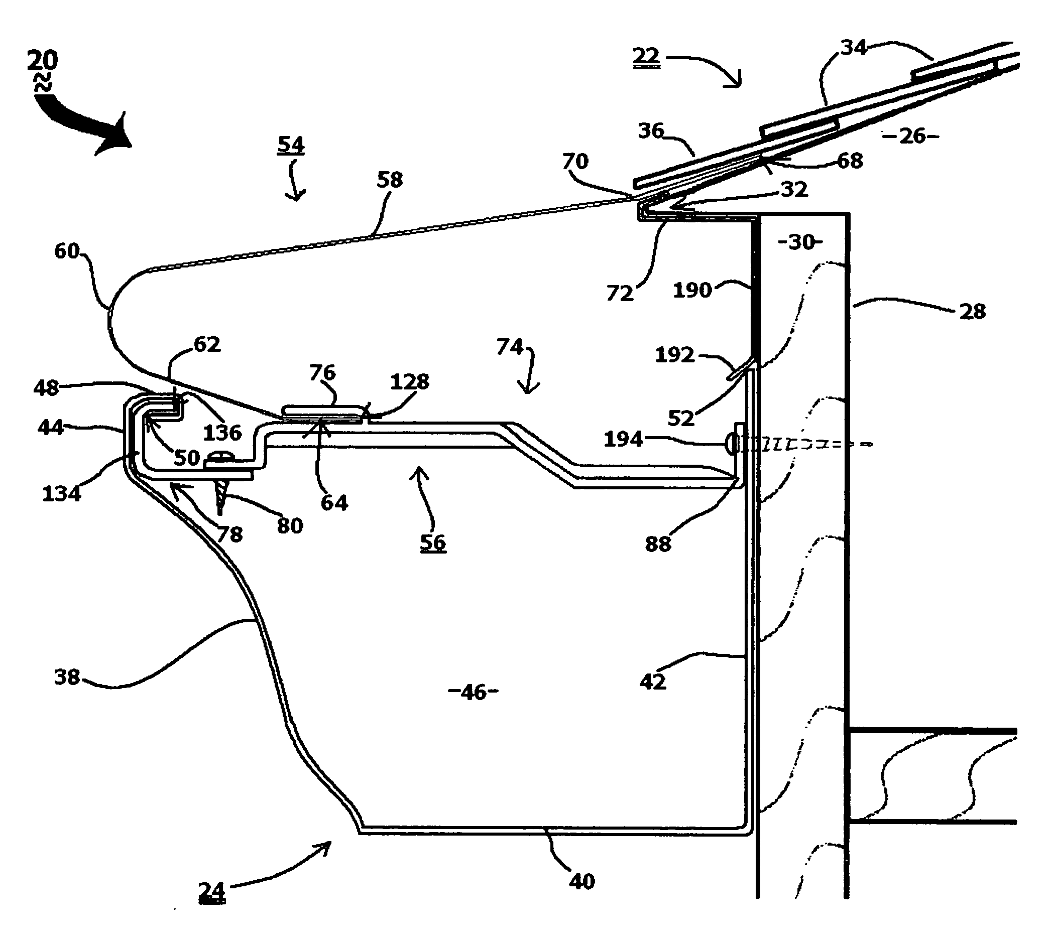
[0027]Referring now to the drawings in general and FIG. 1 in particular, the inventive gutter cover system 20 is shown mounted on a house 22 in operative association therewith, as well as a gutter 24. House (or other building or residential structure) 22 includes a roof deck 26, outer wall 28, fascia 30, roof edge 32, shingles 34, including a lower most shingle 36.

[0028]Gutter 24 includes a front wall 38, a gutter floor 40, back wall 42, a K-style lip 44 and an interior gutter trough 46. Lip 44 has uppermost portions 48 and an interior portion 50. Backwall 42 of gutter 24 has an upper edge 52.

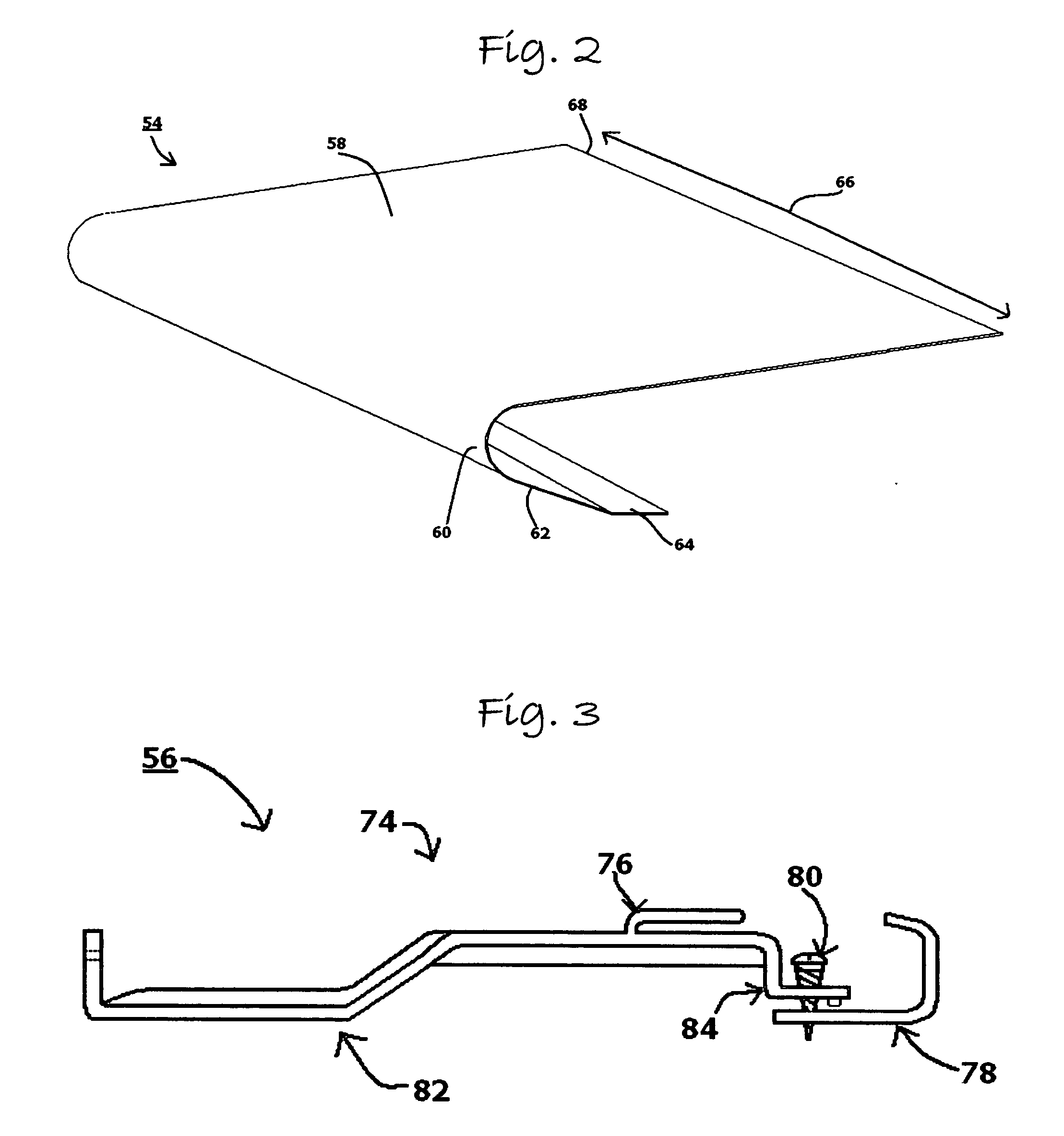
[0029]Gutter cover system 20 has a gutter cover 54 and a gutter bracket 56 according to the present invention.

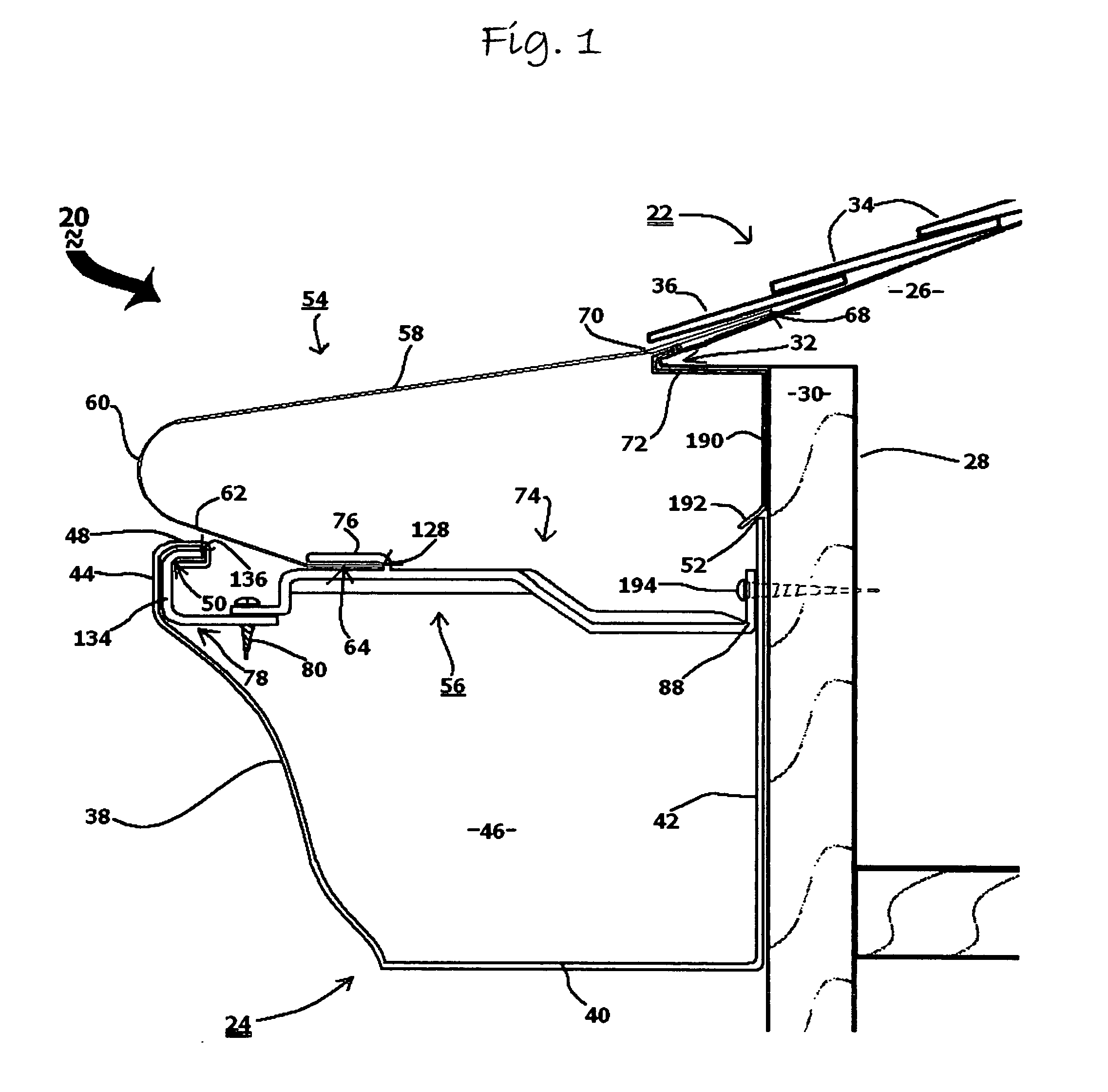
[0030]Referring to FIG. 2, gutter cover 54 is shown in perspective by itself. Gutter cover 54 has a planar, upper panel 58, an arcuate nose 60, a lower member 62 and a planar foot 64. Gutter cover 54 is preferably made of aluminum, or alternatively made of copper or a suitable alloy. Co...


PUM


Abstract

An improved gutter cover system which is relatively convenient to install, with an innovative gutter bracket and gutter cover that can be installed more quickly and effectively.The gutter bracket has a bracket member, a tab member and a lip member. The bracket presents a longitudinal axis aligning the wall end and the swivel end. The bracket includes a shaft with a wall end and a swivel end. The wall end has a flange opposite from the swivel end as well as a flat portion along the longitudinal axis. The tab member extends upwardly from the bracket member, to form a slot adapted for insertion of the edge of the gutter cover. The lip member is affixed to the swivel edge, preferably by a screw. The lip member is configured to be matingly received within the lip of the gutter.The improved gutter cover includes a planar panel for positioning on the roof, an arcuate nose at the lowest portion of the panel disposed close to the gutter, a planar lower member below the nose and a foot suitable for mating edge insertion into the slot.The system improvements include a modified nose with an arcuate profile free of formed edges to avoid diversion of the rainwater path. Another improvement is the foot, which provides a mechanically secure placement of the cover between the roof and the bracket. In particularly preferred embodiments, the bracket presents a raised elevation for easier installment of the cover.In addition, an improved gutter hanger and the gutter bracket are both easier to install, spanning the gutter from front to back, because of a swivel function preferably disposed relatively close to the front of the gutter, for easier installation, yet providing mechanical support for the gutter when the swivel portion is locked into rigid alignment.Both the bracket and hanger are installed in the same fashion. Each is installed by first placing the lip member in mating engagement within the lip of the gutter. Then the flange is fixed to the wall of the building by a screw, bolt or the like. Then the swivel end is securely aligned with the wall end for appropriate mechanical tension between the lip and the wall. At that point the bracket (or hanger) is “locked in” preferably by fixing the screw to both the swivel end and the wall end at their junction.

Description

FIELD OF THE INVENTION[0001]This invention relates to gutter cover systems. More particularly, the invention relates to a gutter cover system with an improved gutter bracket and cover.DESCRIPTION OF RELATED ART[0002]For centuries, architects and builders have understood the beneficial value of directing rainwater away from structures to prevent damage to exterior walls, windows, doors, foundations, basements, landscaping, and to prevent erosion. The most popular and geographically accepted gutter system is the open channel gutter trough that runs parallel along the roof eaves of a building. Gutter systems are designed to direct rainwater away from buildings; however, if clogged with debris, they will fill up and overflow, and since the gutter is located at the buildings roof edge, overflowing water can now damage the interior, as well as the exterior, of the building. In order to accomplish the intended purposes, the gutter system must function properly, and to do this, the gutter t...

Claims


Application Information

Patent Timeline
Patent Type & Authority Applications(United States)
IPC IPC(8): E04D13/00
CPCE04D13/076
Inventor DOWLING, EDNA F.DOWLING, TORRY B.
Owner DOWLING EDNA F
Why Eureka
Try Eureka