Current and voltage measurement device

a current and voltage measurement and power cable technology, applied in the direction of magnetic measurement, measurement using dc-ac conversion, instruments, etc., can solve the problems of preventing damage to the device, affecting the accuracy of current measurement, so as to achieve the effect of easy and safe determination of current flow

Active Publication Date: 2010-07-13
VERTIV CORP
View PDF12 Cites 41 Cited by
  • Summary
  • Abstract
  • Description
  • Claims
  • Application Information

AI Technical Summary

Benefits of technology

[0009]Accordingly, the present invention is directed to a current and / or voltage measurement device that allows a user to easily and safely determine current flow by clamping a semi-permanent wrap-around monitor at any position around the power cable without modifying the cable. In embodiments of the invention, the measuring device comprises a plurality of ring-mounted magnetic field sensors which sense magnetic fields produced by the electrical current in the conductors. In other embodiments, the measurement device may include a plurality of electric field sensors in addition to or in place of the magnetic field sensors, which sense electric fields produced by the electrical current in the conductors.

Problems solved by technology

In such power strips, if the power consumed exceeds the limit of the circuit breaker, the electrical device will be abruptly disabled to prevent damage to the device.
Such a value is not particularly useful when conducting power strip-specific analysis (e.g., determining how many more devices can be plugged into a given power strip before the individual power strip circuit breaker trips).
However, such toroidal transformers 100 are not effective for use in pre-existing electrical cables of power strips because the incoming 103 and outgoing 104 electrical currents create opposing magnetic fields which cancel each other.
Several disadvantages exist with respect to such a method.
Second, the devices being powered by the power cable 200 should be powered down during addition of the current transformer 201 as a safety precaution, thereby causing undesired system downtime for the devices connected to the power strip.
First, the equipment has to be powered off before the break-out box can be inserted, again resulting undesirable system downtime, or, alternately, removing the outer insulation on the conductors while the circuit is powered to avoid system downtime, thereby creating a potentially dangerous situation.
Second, the value obtained by such manual measurements may quickly become out-of-date as equipment is added or removed from the power strip, thereby requiring repeated measurements.

Method used


Image

  • Current and voltage measurement device
  • Current and voltage measurement device
  • Current and voltage measurement device

Examples


Embodiment Construction

[0023]Reference will now be made in detail to the presently preferred embodiments of the invention, examples of which are illustrated in the accompanying drawings.

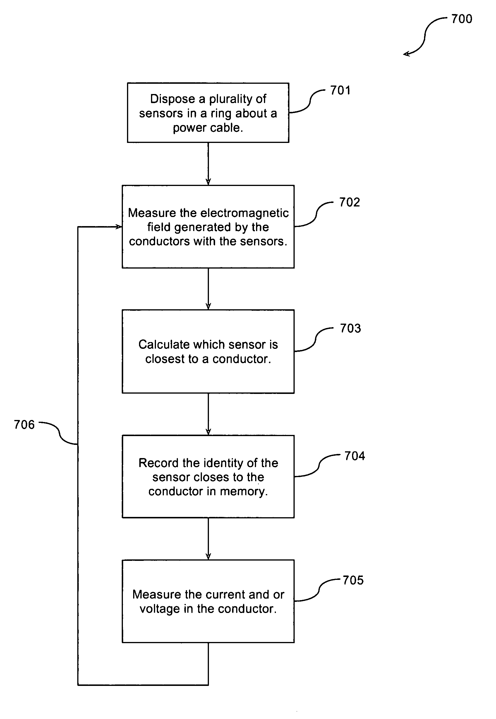
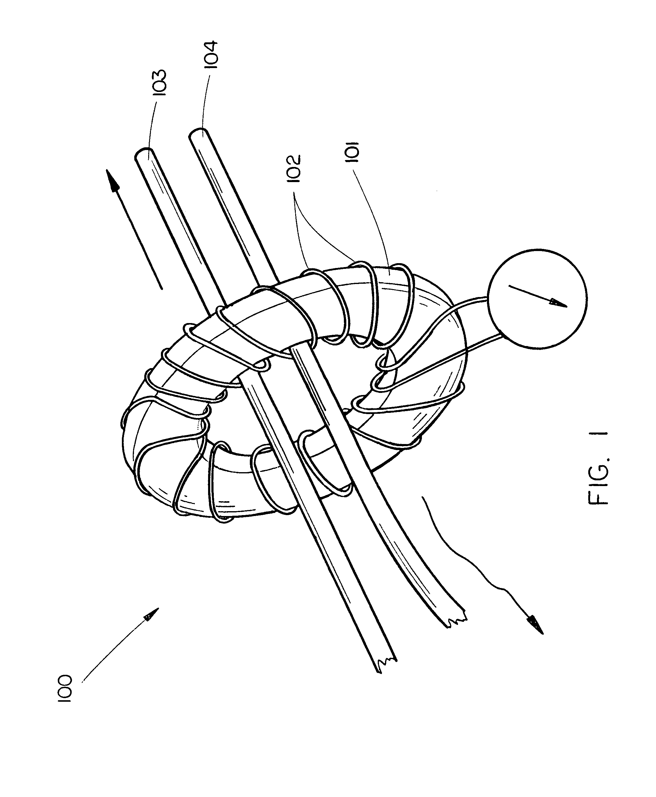
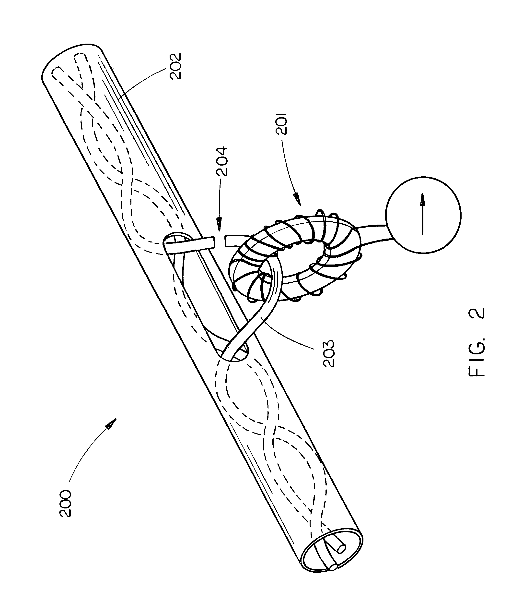
[0024]FIG. 3A illustrates the operation of a current and / or voltage measuring device 300 in accordance with an exemplary embodiment of the present invention. The measurement device allows a user to easily and safely determine current flow by clamping a semi-permanent wrap-around monitor 301 around a power cable 302 without modifying the cable 302.

[0025]In conventional power cable implementations, current carrying conductors 305A and, optionally, a ground conductor 305B within the cable are twisted into a bundle before the outer insulation 310 is applied. As such, the location of either of the current-carrying conductors 305A cannot be determined by visual inspection. Therefore, a primary problem with measuring the current or voltage in such cables is determining the proper position for a magnetic or electric field sensor d...


PUM


Abstract

The present invention is directed to a current and/or voltage measurement device that allows a user to easily and safely determine current flow by clamping a semi-permanent wrap-around monitor around the power cable without modifying the cable may comprise a plurality of ring-mounted magnetic field sensors which sense magnetic fields produced by the electrical current in the conductors and analysis circuitry for calculating the current in those conductors based on the magnetic field values. In other embodiments, the measurement apparatus may include a plurality of electric field sensors in addition to or in place of the magnetic field sensors, which sense electric fields produced by the electrical current in the conductors which may be used to calculate the voltage in the conductors.

Description

CROSS-REFERENCE TO RELATED APPLICATION[0001]This application claims priority from Provisional Application Ser. No. 60 / 812,579 filed on Jun. 8, 2006, which is hereby incorporated by reference in its entirety.FIELD OF THE INVENTION[0002]The present invention generally relates to the current and voltage measurement devices, and more particularly to an device for measuring current and / or voltage in a power cable that allows a user to easily and safely determine current flow and / or voltage in a power cable without modifying the cable by clamping a semi-permanent wrap-around monitor around the power cable.BACKGROUND OF THE INVENTION[0003]Many electrical devices, especially computers and related network equipment, use power strips for electric power distribution. In such power strips, if the power consumed exceeds the limit of the circuit breaker, the electrical device will be abruptly disabled to prevent damage to the device. However, in many applications, such as web or e-mail servers, s...

Claims


Application Information

Patent Timeline
Patent Type & Authority Patents(United States)
IPC IPC(8): G01R15/20
CPCG01R15/20G01R15/148
Inventor CULLEN, GERARD L.SMITH, MICHAEL V.
Owner VERTIV CORP
Why Eureka
Try Eureka