
Implantable electrode lead and hydrogel sensor

a technology of hydrogel sensor and implanted electrode lead, which is applied in the field of medical engineering, can solve the problems of unable to make reliable clinical prognosis, the electrodes and the surrounding tissue layers will heat up, and the implanted electrode lead is typically denied an examination,

Inactive Publication Date: 2013-10-22
BIOTRONIK SE & CO KG
View PDF8 Cites 0 Cited by
  • Summary
  • Abstract
  • Description
  • Claims
  • Application Information

AI Technical Summary

Benefits of technology

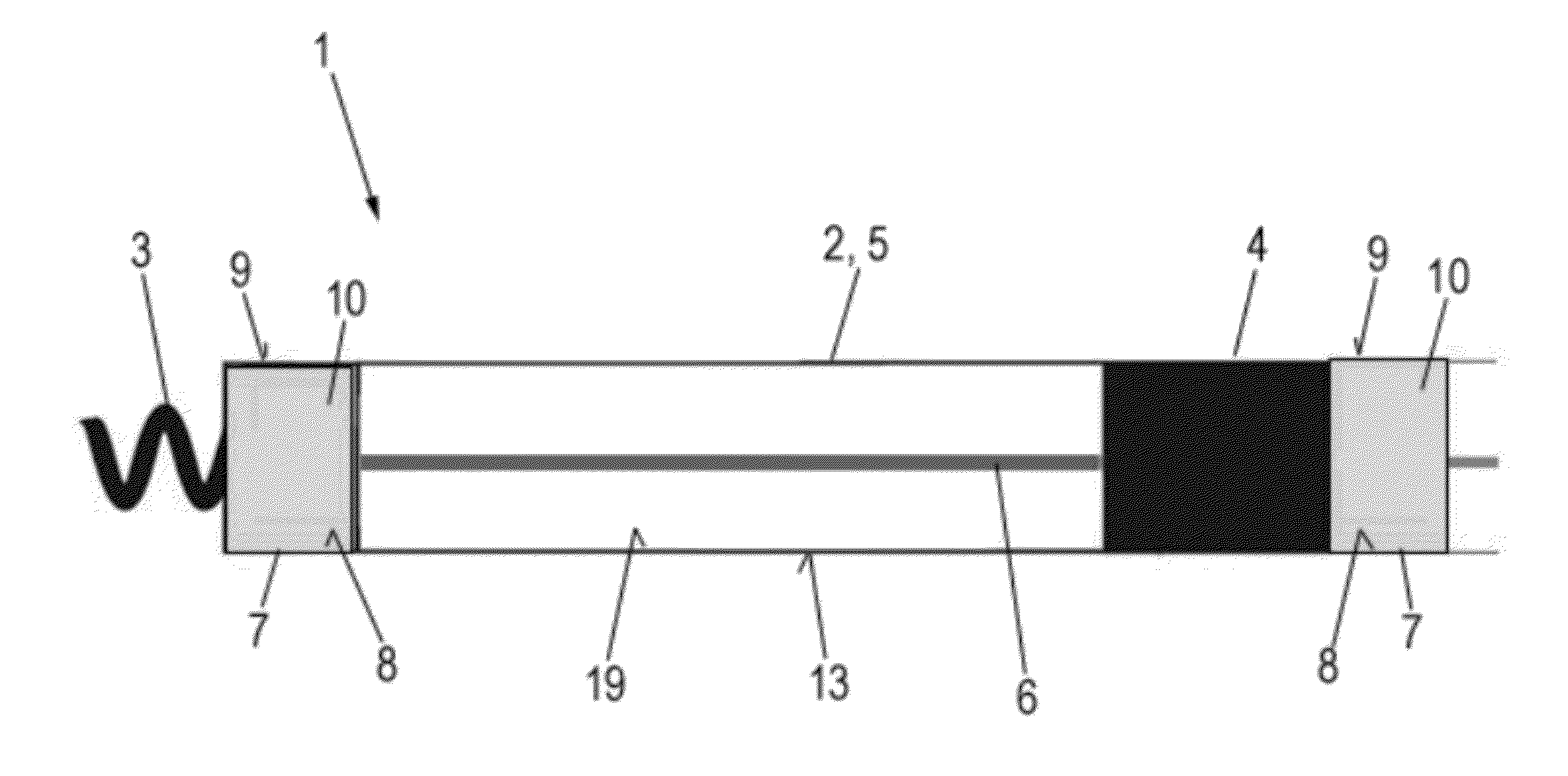
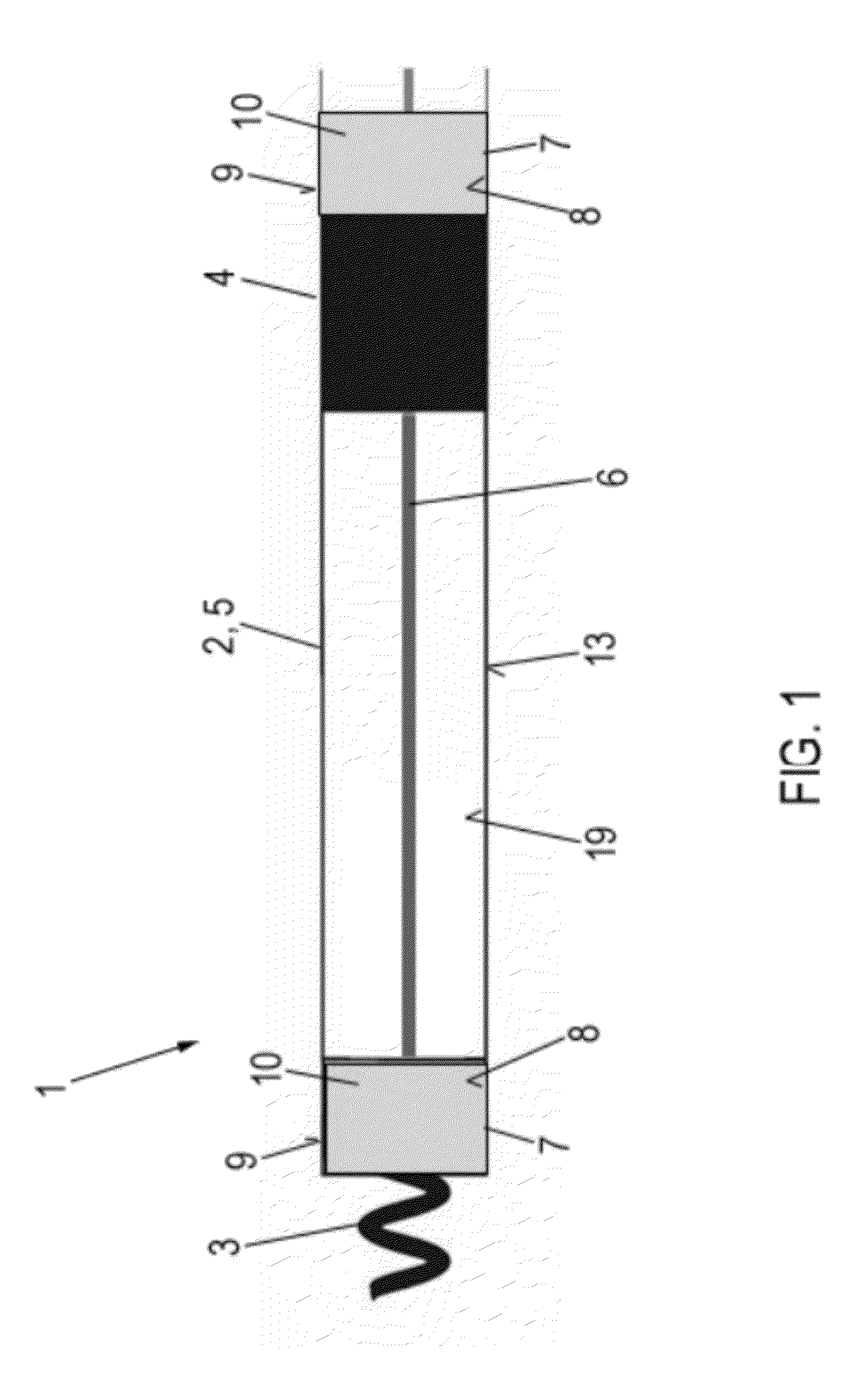
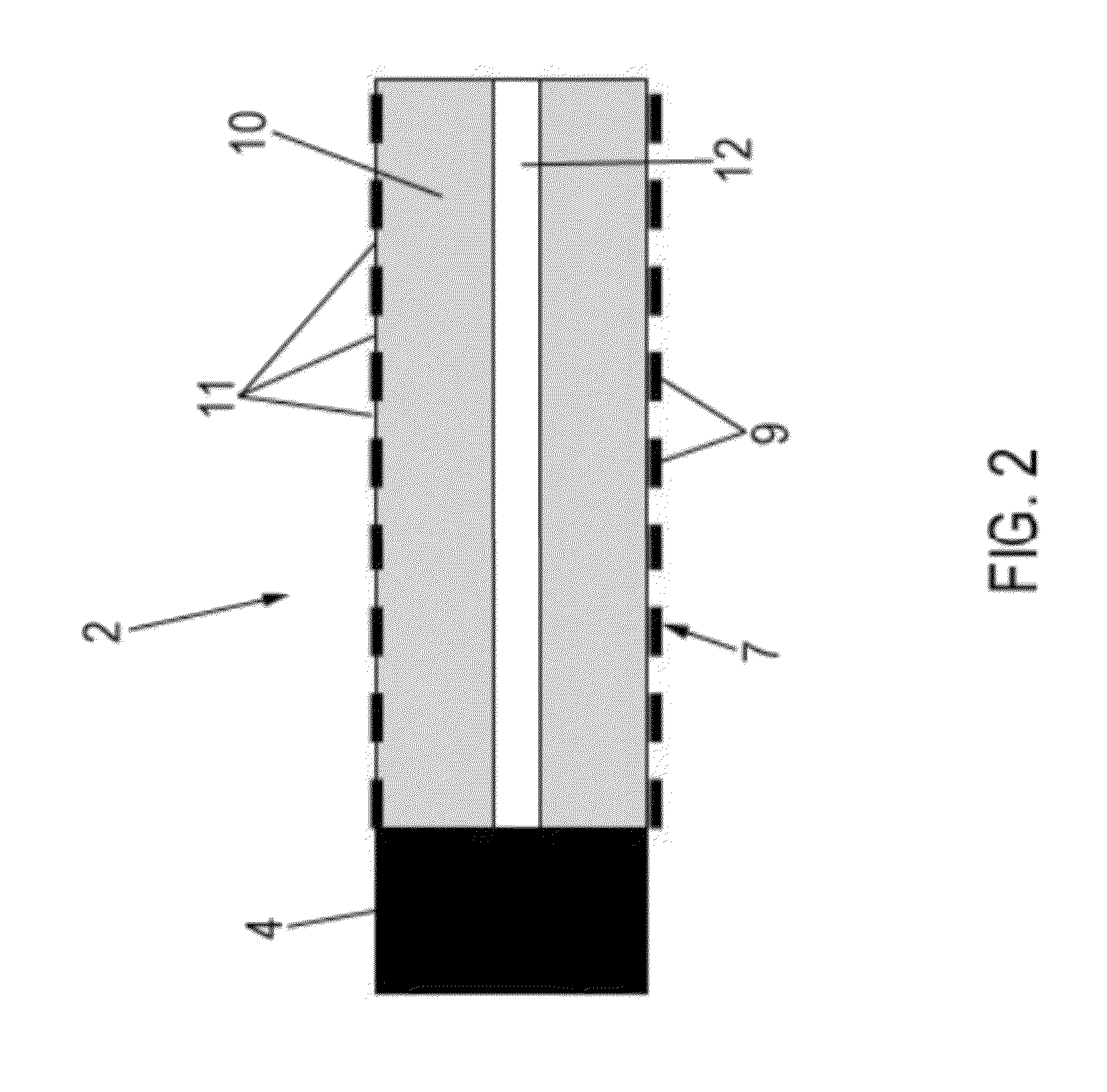
The invention is a hydrogel sensor that can be used in a variety of applications to detect changes in temperature. The sensor includes a hydrogel capsule with a water-permeable wall that is connected to a guide wire or electrode lead. The hydrogel capsule is designed to adapt to the volume of water it contains, which changes due to heating or cooling. The size of the hydrogel capsule can be easily determined using a nuclear resonance tomographic image. The sensor can be safely and easily installed, and it provides a reliable and accurate way to measure temperature.

Problems solved by technology

As is known per se to a person skilled in the art, electrode leads that are present in a patient's body can cause problems during an examination using a nuclear resonance tomograph.
However, when a patient has an implanted electrode lead, there is a risk that its electrodes and the surrounding tissue layers will heat up.
This situation is made more difficult by the fact that the heating of the electrodes depends on the particular scan parameters of the examination and, in particular, on the positioning of the electrode lead in the electromagnetic alternating field, thereby often rendering it impossible to make reliable prognoses in clinical practice.
As a result, patients who have an implanted electrode lead are typically denied an examination using nuclear resonance tomography, which is harmless per se.

Method used


Image

  • Implantable electrode lead and hydrogel sensor
  • Implantable electrode lead and hydrogel sensor
  • Implantable electrode lead and hydrogel sensor

Examples


Embodiment Construction

[0046]FIG. 5 shall be considered first; it shows a schematic depiction of an electrode lead 101 that is permanently implanted in a heart 105 and is well-known in the prior art. Electrode lead 101 is designed e.g. as a shock electrode lead in this case. It has a distal section 103 and a proximal end 102 which is connected to an implanted ICD 104 (implantable cardioverter / defibrillator). This is a device that can generate shock pulses e.g. to terminate a life-threatening ventricular fibrillation. Electrode lead 101 extends through right atrium 106 and is positioned via its distal section 103 inside right ventricle 107. Distal section 103 is provided with a shock electrode 108 designed in the form of a helical wire, and which is in contact with the wall of ventricle 107. The oblong helical shape of shock electrode 108 serves to enlarge the effective electrode surface. Distal section 103 furthermore includes a ring electrode 109 and a conical point electrode 110, which can be used for p...


PUM


Abstract

An implantable electrode lead that includes a distal section having at least one electrode for transmitting electrical energy between the electrode lead and its surroundings. The electrode lead includes at least one hydrogel capsule that is thermally coupled to the electrode, the hydrogel capsule having a water-permeable wall that forms a cavity containing a hydrogel having a temperature-dependent swelling capacity, the wall of the hydrogel capsule being designed such that it can adapt to the volume of the hydrogel. Further relates to an electrode lead assembly, in the case of which a guide element is provided for guiding an electrode lead having a hydrogel capsule of this type. Further relates to a hydrogel sensor that comprises a hydrogel capsule of this type. Furthermore, at least one embodiment of the invention relates to methods used to determine the size of the hydrogel capsule for the purpose of determining the temperature of an electrode, or environment, that is thermally coupled to the hydrogel capsule.

Description

[0001]This application claims the benefit of U.S. Provisional Patent Application 61 / 385,565, filed on Sep. 23, 2010, the specification of which is hereby incorporated herein by reference.BACKGROUND OF THE INVENTION[0002]1. Field of the Invention[0003]One or more embodiments of the invention are based in the field of medical engineering and relates to an implantable electrode lead, and an electrode lead assembly. One or more embodiments of the invention furthermore relates to an implantable hydrogel sensor and its use. Furthermore, at least one embodiment of the invention relates to a method to determine the temperature of the electrode of an electrode lead, and a method for operating a nuclear magnetic resonance tomograph, and its use.[0004]2. Description of the Related Art[0005]Electrode leads of the type in question are known in various embodiments and are used routinely e.g. in the field of electrophysiology to detect and treat conduction defects in the heart or the nervous syste...

Claims


Application Information

Patent Timeline
Patent Type & Authority Patents(United States)
IPC IPC(8): A61N1/02
CPCA61N1/0496A61N1/05A61N1/3718A61N2001/086A61N1/086
Inventor DOERR, THOMAS
Owner BIOTRONIK SE & CO KG
Learn More