

Nagata cycle rotary engine
a rotary engine and cycle technology, applied in the direction of liquid fuel engines, machines/engines, rotary piston liquid engines, etc., can solve the problems of rotary engines that have not enjoyed wide-spread production or success, rotary engines have been plagued by several problems, and significant ones still exist, so as to achieve superior gas mileage and performance.
- Summary
- Abstract
- Description
- Claims
- Application Information
AI Technical Summary
Problems solved by technology
Method used
Image

Examples
example 1
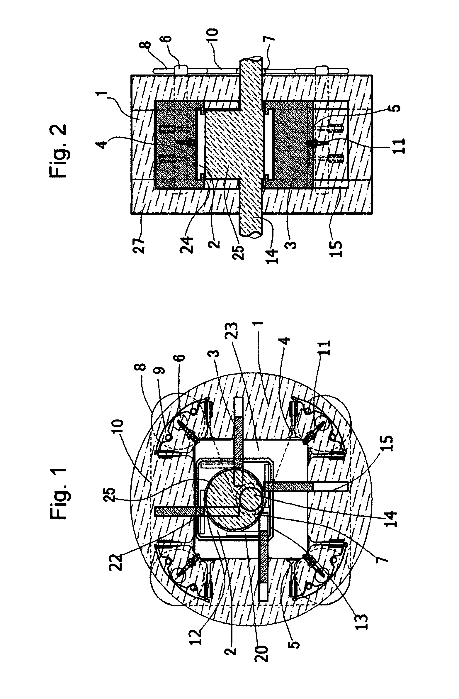
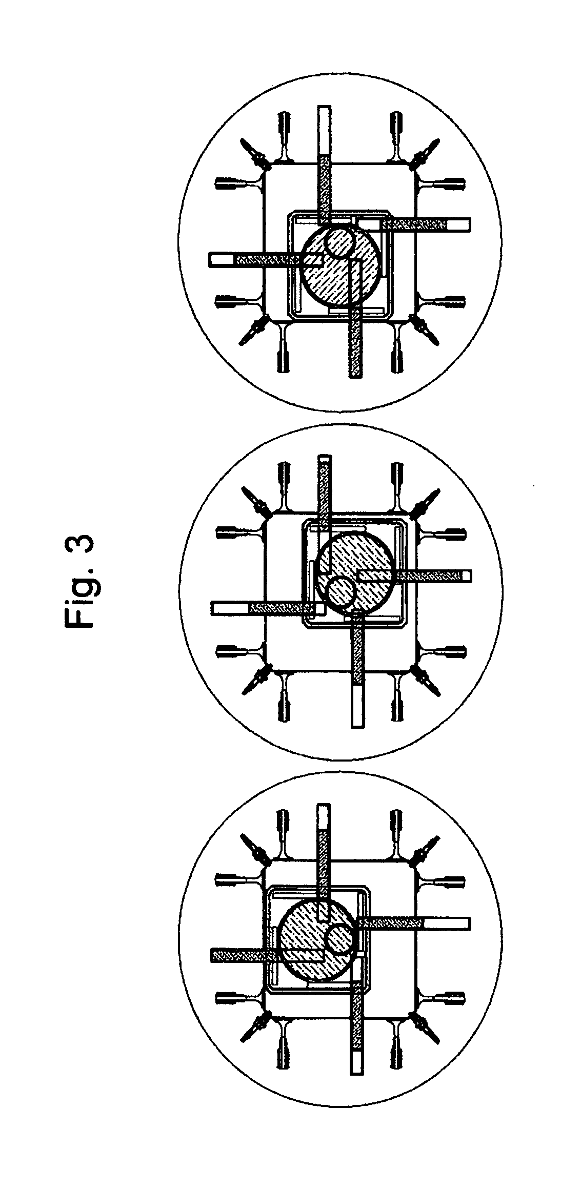
[0021]An embodiment of the present invention is illustrated in FIG. 1. Additionally, FIGS. 4 and 5 depict possible embodiments with different shapes and numbers of working engine chambers.
[0022]The engine has housing (1), which in this a case has an inner wall which is a four sided polygon. Rotor (2), which in this case is also a four sided polygon, is contained inside housing (1) and is positioned off-center of drive shaft (14), allowing it to displace the fuel / air mixture about the engine chamber.
[0023]Vanes (3) extending between rotor (2) and the inner wall of housing (1) create separate chamber rooms (23) within the engine and are supported on each end by either rotor-side vane pins (22) or the vane recess (15) they slide in and out of in the side housing. Vane motion is restricted to rolling freely along, vane channels (12) located in the inner wall of each end housing. Vane pin slots (20) located around the periphery of rotor (2) allow the rotor to be in slideable contact with...
example 2
[0038]An embodiment of the present invention is illustrated in FIG. 5.
[0039]The engine has housing (1), which in this case has an inner wall which is a six sided polygon. Rotor (2), which in this case is also a six sided polygon, is contained inside housing (1) and is positioned off-center of drive shaft (14), allowing it to displace the fuel / air mixture about the engine chamber. Other possible embodiments of this design include any rotor and housing inner surface combination with a polygon shape with an even number of sides.
[0040]Inside rotor (2) are vane pairs (3) which slide in and out of the rotor and housing (1) to create separate chamber rooms (23) within the engine. Dual vane support shaft (21) having a middle portion disposed about said drive shaft, allows vane pairs (3) movement relative to the drive shaft. Each of the aforementioned vane pairs (3) is supported by and is in slideable contact with vane recess (15) on each side of the housing inner wall allowing both parallel...
example 3
[0055]An embodiment of the present invention is illustrated in FIG. 6. Additionally, FIGS. 7, 8 and 9 depict possible embodiments with different shapes, configurations and numbers of working engine chambers.
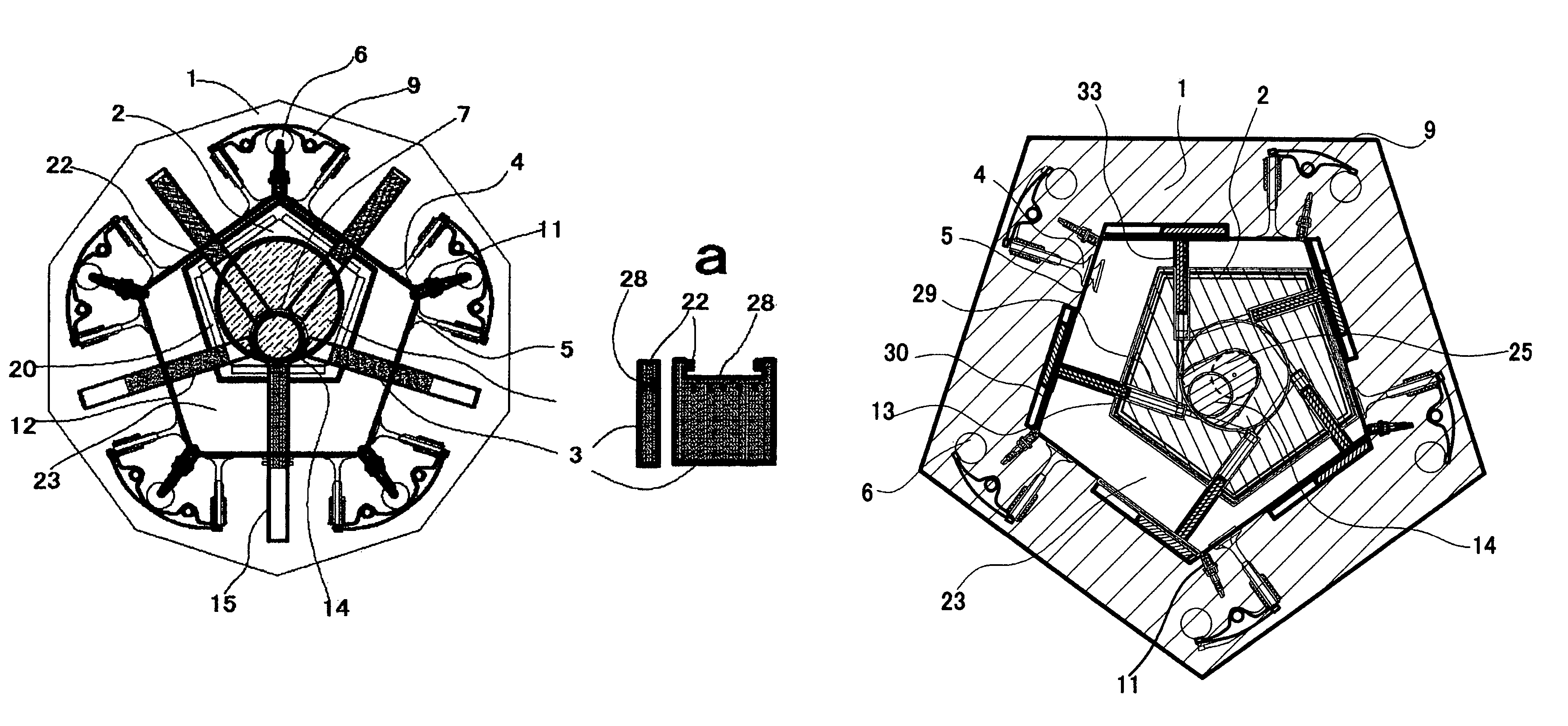
[0056]The engine has housing (1), which in this case has an inner wall which is a five sided polygon. Rotor (2), which in this case is also a five sided polygon, is contained inside housing (1) and is positioned off-center of drive shaft (14), allowing it to displace the fuel / air mixture about the engine chamber.
[0057]Vanes (33) extending between rotor (2) and the inner wall of housing (1) create separate chamber rooms (23) within the engine and are supported on each end by either vane guide (30) or vane recess (29). In this depiction, vanes (33) slide in and out of rotor (2) through vane recess (29) and are in slidable contact with the housing through vane guides (30) located around the periphery of the rotor. This combination of vane recesses and vane guides allows the rotor bo...
PUM
 Abstract
Description
Claims
Application Information