Method for controlling the charging pressure at a turbocharged combustion engine, and a corresponding combustion engine

a technology of turbocharged combustion engine and charging pressure, which is applied in the direction of electrical control, combustion engine, valve arrangement, etc., can solve the problems of reducing affecting the operation of the combustion engine, and the attendant risk of engine damage, so as to reduce the exhaust gas flow through the exhaust turbine, reduce and limit the charging pressure of the engin

Inactive Publication Date: 2005-04-26
SAAB AUTOMOBILE AB
View PDF8 Cites 72 Cited by
  • Summary
  • Abstract
  • Description
  • Claims
  • Application Information

AI Technical Summary

Benefits of technology

[0006]By making use of the divided exhaust period principle, which is known per se, according to patent specification GB 2 185 286, where the exhaust gas flow is, by means of double exhaust valves, divided into two different flows with one flow to the exhaust turbine and one flow past the exhaust turbine, and changing the proportions between these two flows during operation, it is possible to change and limit the charging pressure in the engine without the assistance of a wastegate valve in the exhaust turbine. This is suitably achieved by changing the opening period of the exhaust valve which guides one flow past the exhaust turbine. By increasing this exhaust gas flow, the exhaust gas flow through the exhaust turbine can be reduced, with attendant lowering of the charging pressure in the engine.

Problems solved by technology

One problem with this solution is that, with a powerful exhaust gas flow, a high charging pressure will be obtained, with an attendant risk of engine damage if the charging pressure becomes too high.
One problem in this connection is that the valve used complicates the turbocompressor used and is forced to work in a high-temperature environment.
Moreover, defective functioning can have disastrous consequences for the engine.

Method used


Image

  • Method for controlling the charging pressure at a turbocharged combustion engine, and a corresponding combustion engine
  • Method for controlling the charging pressure at a turbocharged combustion engine, and a corresponding combustion engine

Examples


Embodiment Construction

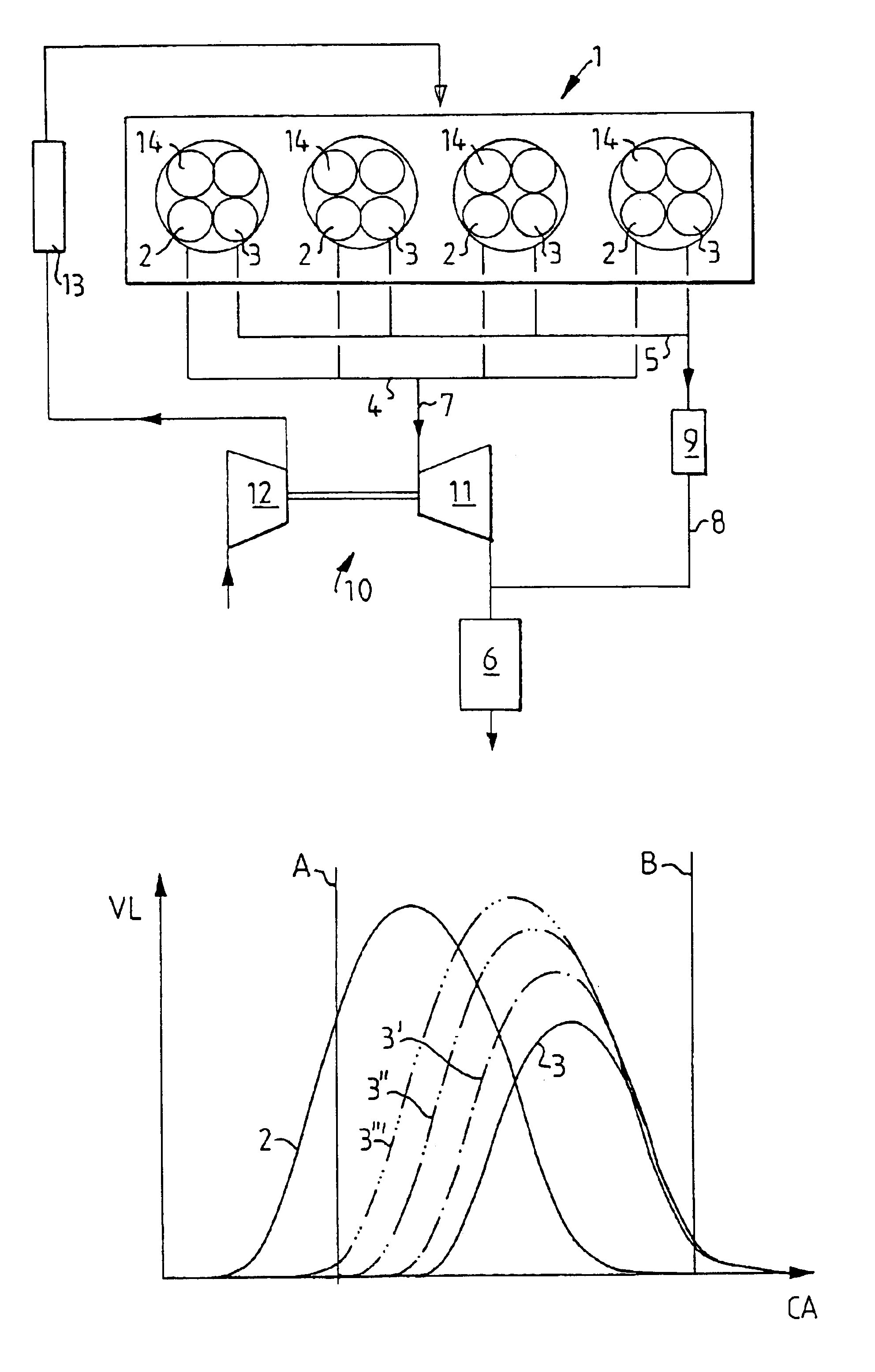
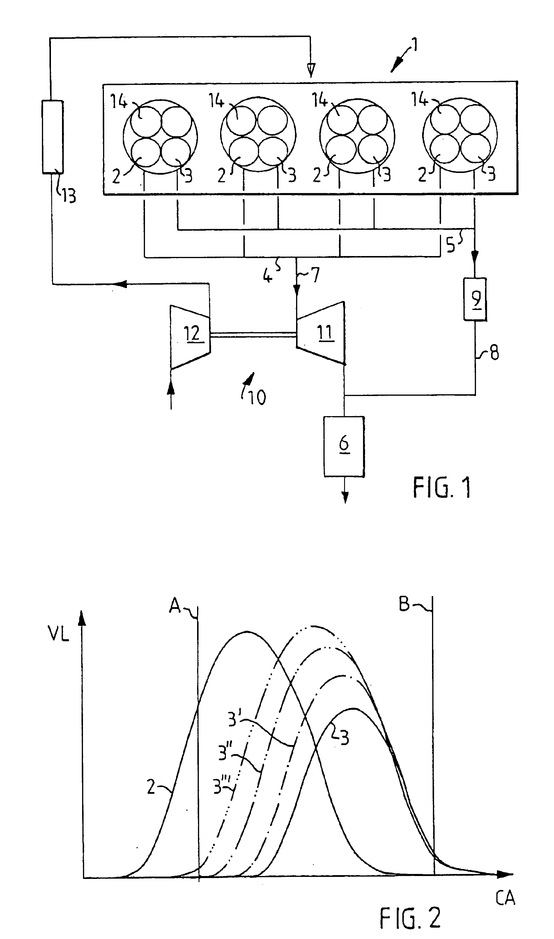
[0012]FIG. 1 shows diagrammatically a multicylinder internal combustion engine 1 according to the invention in the form of an Otto engine. The cylinders of the engine each have at least two exhaust valves 2 and 3. Exhaust gases are conducted out from the first exhaust valves 2 of the cylinders to a first exhaust manifold 4 common to the cylinders. Exhaust gases are conducted out from the second exhaust valves 3 of the cylinders to a second exhaust manifold 5 common to the cylinders. The first exhaust manifold 4 is connected to a first catalyst 6 via a first exhaust line 7, and the second exhaust manifold 5 is connected to the first catalyst 6 via a second exhaust line 8 which here contains a second catalyst 9. One or more silencers (not shown) is or are located downstream of the catalyst 6 in a conventional manner.

[0013]The engine 1 is also equipped for supercharging by means of an exhaust-driven turbocompressor 10 (or turbocharger), the turbine 11 of which is connected in the first...


PUM


Abstract

A multicylinder internal combustion engine with an exhaust-driven turbocompressor and with a divided exhaust gas flow has at least two exhaust valves (2,3) and one intake valve per cylinder. A first exhaust valve (2) is connected to a first exhaust manifold which leads to the turbine of the compressor, while a second exhaust valve (3) is connected to a second exhaust manifold which opens downstream of the turbine. The charging pressure in the engine can be regulated by virtue of the opening periods of the exhaust valves (2,3) being varied in relation to one another in order to adapt the flow through the exhaust turbine to a value which provides the desired charging pressure in the engine. By opening the second exhaust valve (3) increasingly earlier, an increasingly lower charging pressure can be achieved.

Description

TECHNICAL FIELD[0001]The invention relates to on the one hand a method for controlling the charging pressure in an internal combustion engine and particularly to set a desired charging pressure in the engine.STATE OF THE ART[0002]Within vehicle technology, use is frequently made of the supercharging of internal combustion engines in order to achieve greater engine power at great speed. Supercharging is achieved in this connection by means of a compressor driven by the engine. A common solution is for such a compressor to be driven by an exhaust turbine driven by the exhaust gases of the engine. One problem with this solution is that, with a powerful exhaust gas flow, a high charging pressure will be obtained, with an attendant risk of engine damage if the charging pressure becomes too high.[0003]According to a known solution to this problem, the exhaust turbine is provided with a safety valve, what is known as a wastegate valve, which, at a predetermined pressure in the compressor o...

Claims


Application Information

Patent Timeline
Patent Type & Authority Patents(United States)
IPC IPC(8): F02D23/00F02D13/02F02B37/18F01L1/34F01L13/00F02B37/02
CPCF02B37/02F02B37/18F02D13/0246F02D23/00F02D13/0257Y02T10/144F02D2041/001Y02T10/18Y02T10/12
Inventor EKENBERG, MARTIN
Owner SAAB AUTOMOBILE AB
Why Eureka
Try Eureka