Method of controlling engine system and engine system

a technology of engine system and engine system, applied in the direction of electrical control, process and machine control, instruments, etc., can solve the problems of deterioration of drivability, insufficient control, and inability to obtain smooth torque curve, etc., to achieve the effect of improving drivability

Inactive Publication Date: 2010-08-26
MAZDA MOTOR CORP
View PDF1 Cites 72 Cited by
  • Summary
  • Abstract
  • Description
  • Claims
  • Application Information

AI Technical Summary

Benefits of technology

[0008]An object of the present invention is to provide a method of controlling an engine system or an engine system itself wh

Problems solved by technology

Accordingly, the smooth torque curve may not be obtained, so that the driver may feel uncomfortable feelings and thereby the drivability may deteriorat

Method used


Image

  • Method of controlling engine system and engine system
  • Method of controlling engine system and engine system
  • Method of controlling engine system and engine system

Examples


embodiment 1

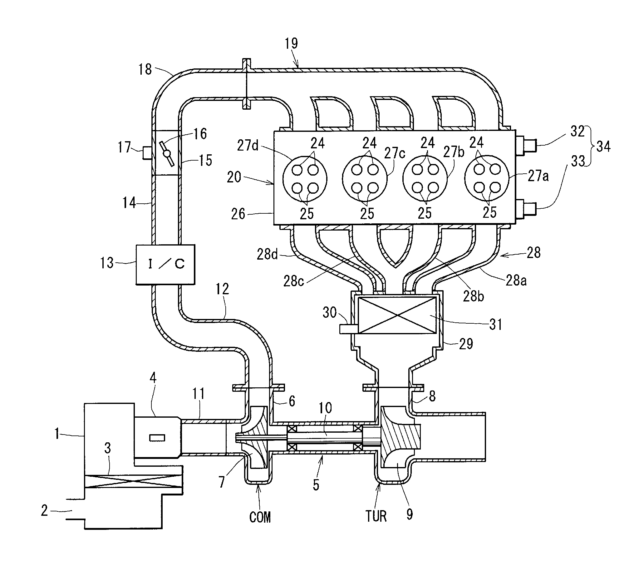
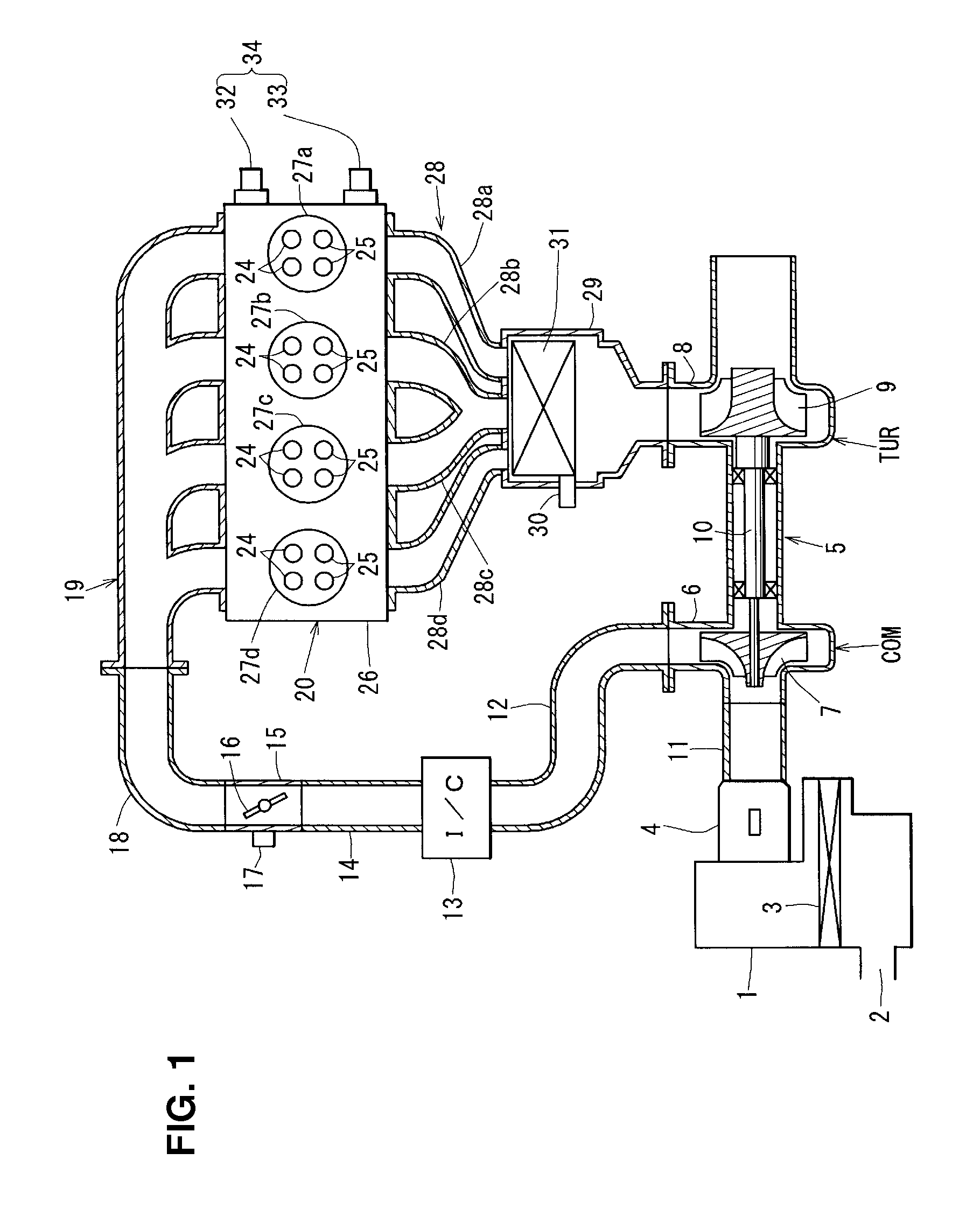
[0037]The drawings show an engine system equipped with a turbo charger and a method of controlling the engine system. First, the engine system will be described referring to FIG. 1. An intake system of the engine system comprises an air cleaner 1 which purifies intake air. The air cleaner 1 has an inlet 2 and an element 3. An airflow sensor 4 which detects the amount of the purified intake air from the air cleaner 1 with its voltage change is provided downstream of the element 3 of the air cleaner 1.

[0038]A turbo charger 5 is arranged between the intake system and an exhaust system of the engine system. The turbo charger 5 comprises a compressor impeller 7 which is arranged in a compressor housing 6 of the intake system and a turbine wheel 9 which is arranged in a turbine housing 8 of the exhaust system. The compressor impeller 7 and the turbine wheel 9 are interconnected by a rotational shaft 10. The turbine wheel 9 is rotated by the exhaust gas of the engine system and the compres...

embodiment 2

[0088]A second embodiment using the CVVL (Continuously Variable Valve Lift) system which can change the amount of lift of the intake valve 24, for example, with using a motor regardless of the rotation of a crankshaft along with the valve opening / closing timing of the intake valve 24 will be described. The intake-valve closing timing IVC is set to be advanced by a specified angle from the bottom dead center BDC of the intake stroke as shown in FIG. 11A. Herein, as the desired torque of the engine increases in accordance with the engine acceleration, the lift amount IN of the intake vale 25 is increased as shown in FIG. 11B so that the intake-valve closing timing IVC is retarded so as to be closer to the bottom dead center BDC of the intake stroke. After that, as shown in FIG. 11C, the intake-valve opening timing IVO is advanced so that the valve overlap period is increased.

[0089]Accordingly, since the intake-valve closing timing IVC can be made closer to the bottom dead center BDC o...

embodiment 3

[0090]A third embodiment using the phase type of valve timing changing mechanism VVT which changes the opening / closing timing of the intake valve 24 and the exhaust valve 25, keeping the valve open period of these valves 24, 25 constant will be described. Herein, a possibility of abnormal combustion, such as knocking, occurring in the combustion chamber is determined (corresponding to a step S34, which will be described below) at the engine acceleration and the control is executed based on the detection result.

[0091]As shown in FIG. 12, the engine driving conditions, such as the throttle opening TVO, the engine speed Ne, and an intake-air temperature Tin, are detected (step S31). Then, a basic phase angle θvvt of the intake valve 24 and the exhaust valve 25 which corresponds to the desired engine torque is calculated based on the above-described detection results (step S32), and a cylinder-inside temperature Tcc is estimated (step S33). Next, the possibility of abnormal combustion, ...


PUM


Abstract

A valve overlap period is increased as a desired torque of an engine increases by advancing an opening timing of an intake valve at a rate greater than that of retarding a closing timing of an exhaust valve in a low engine-torque area in which the desired torque of the internal combustion engine is relatively low (step S16). The valve overlap period is increased as the desired torque of the engine increases by retarding the closing timing of the exhaust valve at a rate greater than that of advancing the opening timing of the intake valve in a high engine-torque area in which the desired torque of the internal combustion engine is relatively high (step S17). Accordingly, the drivability can be improved by obtaining the proper torque and the smooth torque curve in the wide driving area.

Description

BACKGROUND OF THE INVENTION[0001]The present invention relates to a method of controlling an engine system equipped with a turbo charger, which has the function of increasing a valve overlap period during which an intake valve and an exhaust valve are both opened as a desired torque of the engine (i.e., engine load) increases, and the engine system.[0002]It is generally known that when the valve overlap period during which the intake valve and the exhaust valve are both opened is gradually increased from a state shown in FIG. 9A to states shown in FIGS. 9B, 9C and 9D as the desired torque (load) of the engine increases (an area of valve overlap is illustrated with hatching in these figures for convenience) in the engine equipped with the turbo charger, the mount of scavenging gas so increases that the so-called “late burning (combustion)” in which the fresh air and unburned fuel are reacted in an exhaust pipe occurs and the temperature of the exhaust gas flowing to a turbine of the ...

Claims


Application Information

Patent Timeline
IPC IPC(8): F02D41/00F01L1/34F02D23/00
CPCF01L1/344Y02T10/18F02D9/04F02D9/16F02D13/0219F02D13/0226F02D13/0261F02D41/0002F02D41/0007F02D2041/001F02D2250/18F02D2250/21Y02T10/144Y02T10/14F01L13/0015Y02T10/12F02D35/026
Inventor FUJII, MIKIHITOYOKOTA, KAZUYAYAMAGATA, NAOYUKINARAHARA, KAZUAKI
Owner MAZDA MOTOR CORP
Why Eureka
Try Eureka