
Control of exhaust to a turbo of internal combustion engine

a technology of internal combustion engine and control valve, which is applied in the direction of electrical control, machines/engines, output power, etc., can solve the problems of uneven wear of the turbine, poor use of the energy contained in the exhaust gases, and longer for the catalytic converter to reach the working temperature, so as to reduce the back-pressure of the exhaust gas, and improve the efficiency of the engin

Inactive Publication Date: 2006-04-06
SAAB AUTOMOBILE AB
View PDF6 Cites 72 Cited by
  • Summary
  • Abstract
  • Description
  • Claims
  • Application Information

AI Technical Summary

Benefits of technology

[0006] An object of the present invention is to provide an improved internal combustion engine having a supercharging system, which is efficient at partial load and low engine speeds.
[0007] A further object is to provide a simpler supercharging system, which at the same time makes efficient use of the energy present in the exhaust gases.
[0008] Another object is to provide an internal combustion engine having a supercharging system with a long service life.

Problems solved by technology

A disadvantage of these solutions is that they make poor use of the energy contained in the exhaust gases, since two exhaust manifolds have to be heated up when the engine is started up, which means that it takes longer for a catalytic converter to get up to working temperature.
Another disadvantage is that the load on the different turbines is uneven, which can result in uneven wear to the turbines.

Method used


Image

  • Control of exhaust to a turbo of internal combustion engine
  • Control of exhaust to a turbo of internal combustion engine
  • Control of exhaust to a turbo of internal combustion engine

Examples


Embodiment Construction

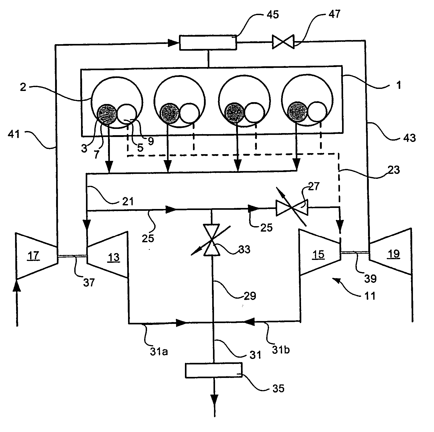
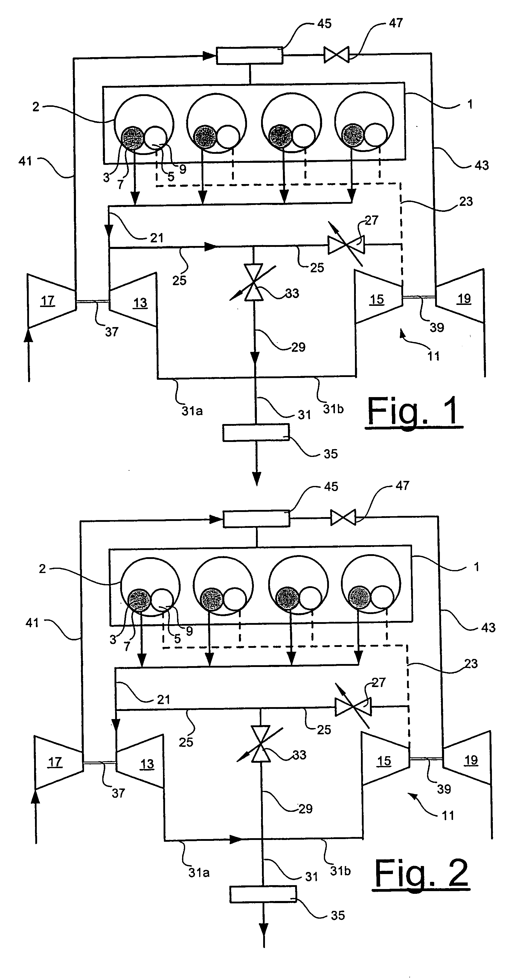
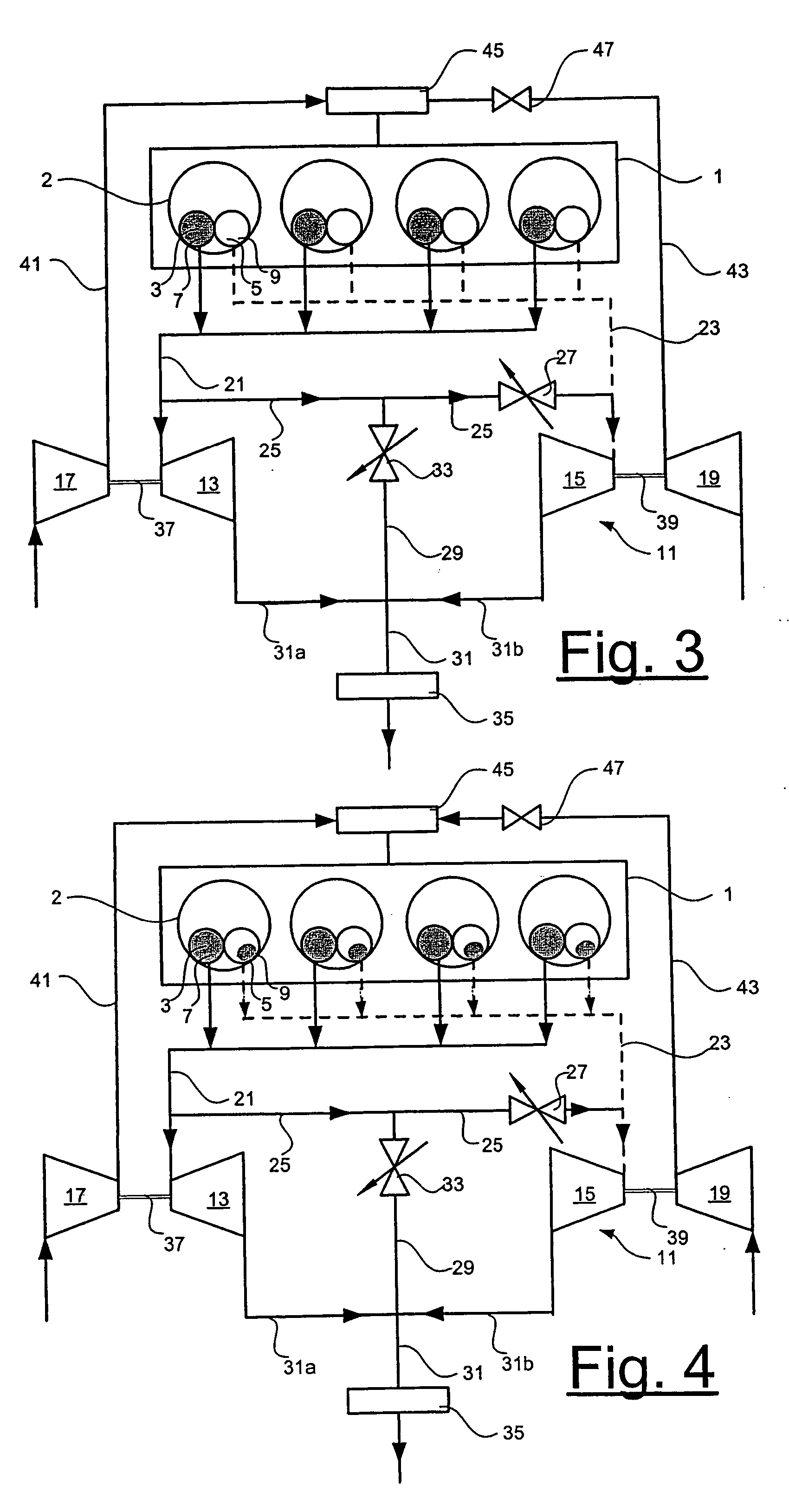
[0028]FIG. 1 shows a schematic representation of an internal combustion engine according to the invention. The internal combustion engine 1, a four-cylinder in-line engine, is equipped with a first and a second exhaust port 3, 5 for each cylinder 2. The first and second exhaust ports are provided with first and second exhaust valves 7, 9 respectively for opening and closing the exhaust ports during operation of the engine. The exhaust valves 7, 9 can be individually controlled independently of one another by either electromechanical, electrohydraulic or pneumatic means, such means of valve control being already known in the art, for which reason they will not be described in more detail. The opening and closing of the valves 7, 9 is preferably continuously adjustable, so that their lift / timing can be varied as a function of the current engine operating condition and relevant parameters, in order to permit a high performance of the internal combustion engine 1. This type of valve con...


PUM


Abstract

An internal combustion engine has a plurality of cylinders, and each cylinder has at least one first and one second exhaust port with associated respective first and second exhaust valves. At least one first and one second exhaust manifold are flow-connected to the respective first and second exhaust ports. A turbo unit for supercharging the charge air delivered to the cylinders comprises at least one first and one second exhaust gas turbine respectively flow connected to the first and the second exhaust manifolds. An exhaust gas chamber flow-connects the first and the second exhaust manifolds upstream of the exhaust gas turbines. The first and second exhaust valves can be deactivated / activated during operation. A throttle valve in the exhaust gas chamber may assume a closed position in order to separate the first and the second exhaust manifolds. A method of operating includes opening and closing different valves at different engine speeds.

Description

TECHNICAL FIELD [0001] The present invention relates to an internal combustion engine and particularly to control over exhaust gas outlet for efficient operation of a turbo. BACKGROUND ART [0002] Current demands for a low fuel consumption and high engine performance from internal combustion engines intended for vehicles have led to ever more powerful supercharging systems. Supercharging systems working in parallel and in tandem, such as two exhaust gas turbines arranged in parallel, where one operates at low engine speeds and the other exhaust gas turbine is only connected at high engine speeds, are already known. One advantage of these systems is that they afford good low-speed characteristics when small volumes of exhaust gas are directed exclusively to the first exhaust gas turbine and good high-speed characteristics when large volumes of exhaust gas are directed to both of the exhaust gas turbines. [0003] The United States patent documents U.S. Pat. No. 4,993,228 and U.S. Pat. N...

Claims


Application Information

Patent Timeline
IPC IPC(8): F02B33/44F02BF02B37/007F02B37/02F02B37/12F02B37/18F02D13/02F02D23/00F02D41/00
CPCF01N13/107F02B37/001F02B37/002Y02T10/144F02B37/02F02B37/18F02D41/0007F02B37/007Y02T10/12F02B37/12F02D13/02F02D23/00
Inventor KARLSSON, ERIK
Owner SAAB AUTOMOBILE AB
Learn More