Fabrication of miniature fiber-optic temperature sensors

Active Publication Date: 2010-07-27
VIRGINIA TECH INTPROP INC
View PDF8 Cites 20 Cited by
  • Summary
  • Abstract
  • Description
  • Claims
  • Application Information

AI Technical Summary

Benefits of technology

[0011]It is thus an object of the present invention to provide a coupling of elements that allows for proper dispersion and proper alignment. It is also an object to provide such a coupl

Problems solved by technology

In both types, the radiation emitted by the fiber lightpipe itself adds to the target radiation and thus constitutes an error source, leaving the measurement sensitive to environmental temperature changes around the lightpipe.
Therefore, in situ calibration is usually required and brings inconvenience to its field application.
That will leave the sensor with quite different sensitivities and performance at difference temperature ranges and therefore

Method used


Image

  • Fabrication of miniature fiber-optic temperature sensors
  • Fabrication of miniature fiber-optic temperature sensors
  • Fabrication of miniature fiber-optic temperature sensors

Examples


Embodiment Construction

[0034]A preferred embodiment of the present invention will be set forth in detail with reference to the drawings, in which like reference numerals refer to like elements or operational steps throughout.

[0035]The present invention is directed to the design and detailed fabrication process of fiber-optic temperature sensors. When properly fabricated, the sensors have been demonstrated to be well-suited for reliable temperature monitoring even in the harshest environments.

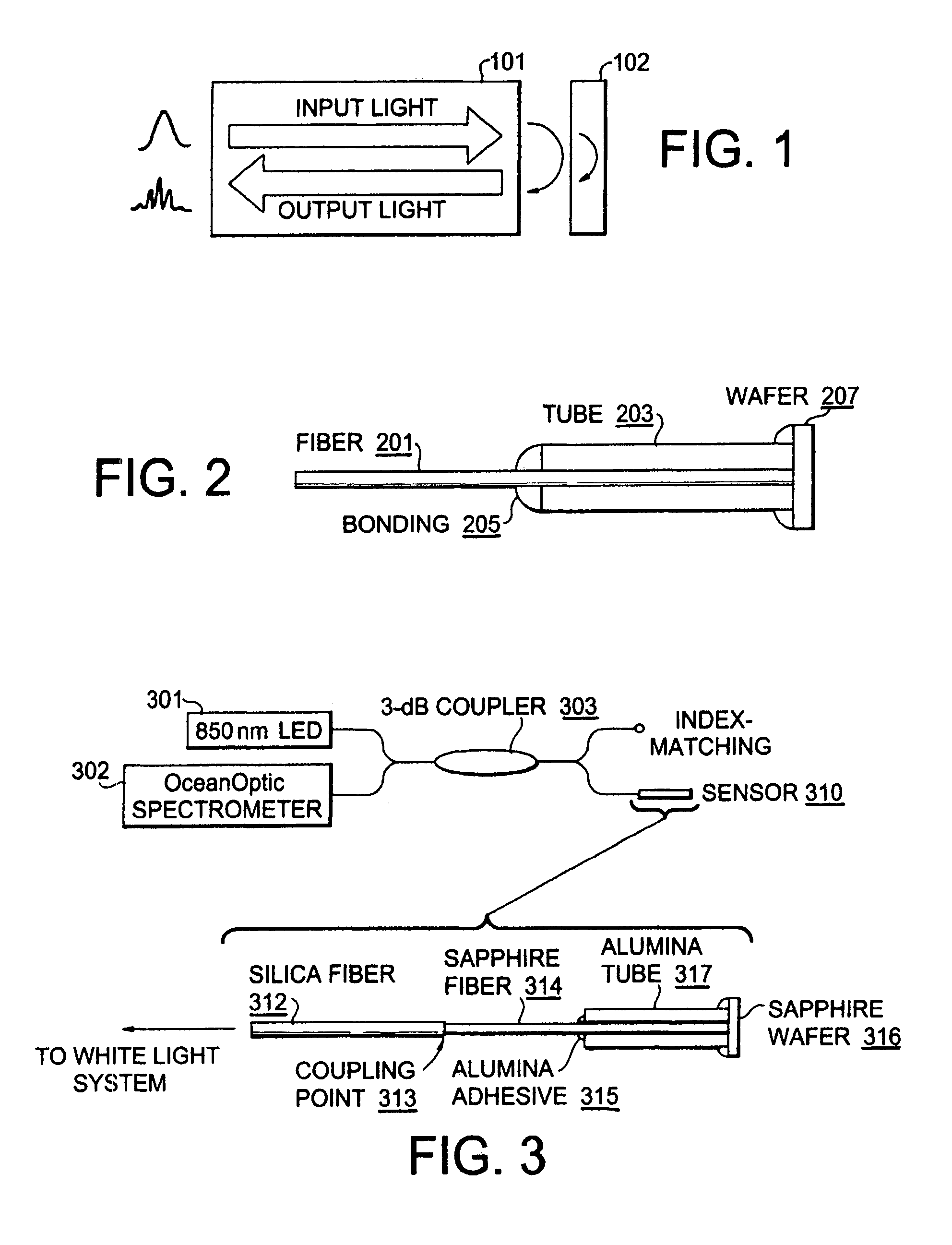
[0036]As illustrated in FIG. 1, the sensing mechanism is based on a wafer 102 whose surfaces create a Fabry-Perot interferometer. A fiber 101 can be used to deliver light to the wafer 102 and receive the reflected signal from which the wafer's optical thickness (OT, product of physical thickness, d, and refractive index n) can be obtained by white-light interferometry. Since both d and n have thermal dependences, OT can serve as an excellent indicator of environmental temperature. The sensor can be made of a variety o...


PUM


Abstract

A method of coupling a silica fiber and a sapphire fiber includes providing a silica fiber having a doped core and a cladding layer, with the doped core having a prescribed diameter, providing a sapphire fiber having a diameter less than the doped core, placing an end of the sapphire fiber in close proximity to an end of the silica fiber, applying a heat source to the end of silica fiber and introducing the end of sapphire fiber into the heated doped core of the silica fiber to produce a coupling between the silica and sapphire fibers.

Description

CROSS-REFERENCE TO RELATED APPLICATIONS[0001]This application claims the benefit of U.S. Provisional Patent Application No. 60 / 836,127, filed on Aug. 8, 2006. The full disclosure of this provisional application is incorporated herein by reference.STATEMENT OF GOVERNMENT INTEREST[0002]This invention was made with Government support under Grant No. DE-FC26-99FT40685 awarded by the Department of Energy. The Government has certain rights in the invention.FIELD OF THE INVENTION[0003]The present invention is directed to temperature sensors. More specifically, the present invention is further directed to the implementation of temperature sensors that that can be used in high-temperature environments.DESCRIPTION OF RELATED ART[0004]Temperature sensing is one of the key topics in fiber-optic sensor research. Numerous schemes have been proposed since the early 1980s for a variety of applications from biological monitoring to industrial sensing. For high temperatures well above 1000° C., singl...

Claims


Application Information

Patent Timeline
IPC IPC(8): G01J5/00G01K11/00
CPCG01J5/08G01J5/0821G01K11/3206G02B6/2551
Inventor ZHU, YIZHENGWANG, ANBO
Owner VIRGINIA TECH INTPROP INC
Why Eureka
Try Eureka