GT-cut quartz crystal resonator

a quartz crystal and resonator technology, applied in piezoelectric/electrostrictive/magnetostrictive devices, impedence networks, piezoelectric/electrostriction/magnetostriction machines, etc., can solve the problem of affecting the vibration of the crystal plate, the inability to arbitrarily set the planar shape and arrange the support portion, and the difficulty in manufacturing such support portions. , to achieve the effect of small and simple configuration without adverse

Inactive Publication Date: 2015-02-17
NIHON DEMPA KOGYO CO LTD
View PDF10 Cites 0 Cited by
  • Summary
  • Abstract
  • Description
  • Claims
  • Application Information

AI Technical Summary

Benefits of technology

[0011]It is an object of the present invention to provide a GT-cut crystal resonator which can be provided with a support portion having a small and simple configuration without adverse effect on vibration characteristics.
[0013]The GT-cut crystal plate, which is conventionally formed in a rectangular shape, is formed in an elliptical shape in the present invention. As described later, in the GT-cut crystal plate of the elliptical shape, there are four points where a minimum vibration displacement is obtained on an outer peripheral portion of the crystal plate. The support portion for supporting the crystal plate is connected to each of such points. According to the present invention, it is possible to support a crystal plate at a substantial stationary position for a vibration displacement and use a support portion having a small and simple configuration without adverse effect on vibration characteristics. Thus, it is possible to obtain a crystal resonator having an excellent temperature characteristic and high stability.

Problems solved by technology

Therefore, it is impossible to arbitrarily set the planar shape and to arrange the support portion at an arbitrary position.
Since the vibration mode of the GT-cut crystal plate is the width-length extensional coupling vibration mode, the crystal plate is vibrated and displaced at the connected positions of the support portions, and the provision of the support portions may thus hinder vibration of the crystal plate.
However, it is difficult to manufacture such support portions, because each support portion has a complicated shape.
Further, the size of the support portion itself cannot be ignored in comparison to the size of the main portion of the vibrating plate.

Method used


Image

  • GT-cut quartz crystal resonator
  • GT-cut quartz crystal resonator
  • GT-cut quartz crystal resonator

Examples


first embodiment

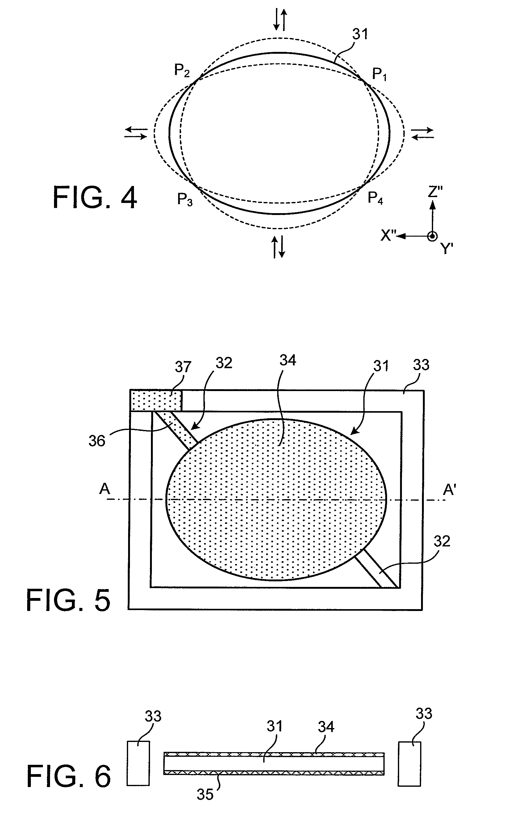
[0028]The quartz crystal resonator shown in FIG. 4 is identical with the crystal resonator of the related art described above in that GT-cut crystal plate 31 is used, but is different from the crystal resonator of the related art in that crystal plate 31 has an elliptic planar shape.

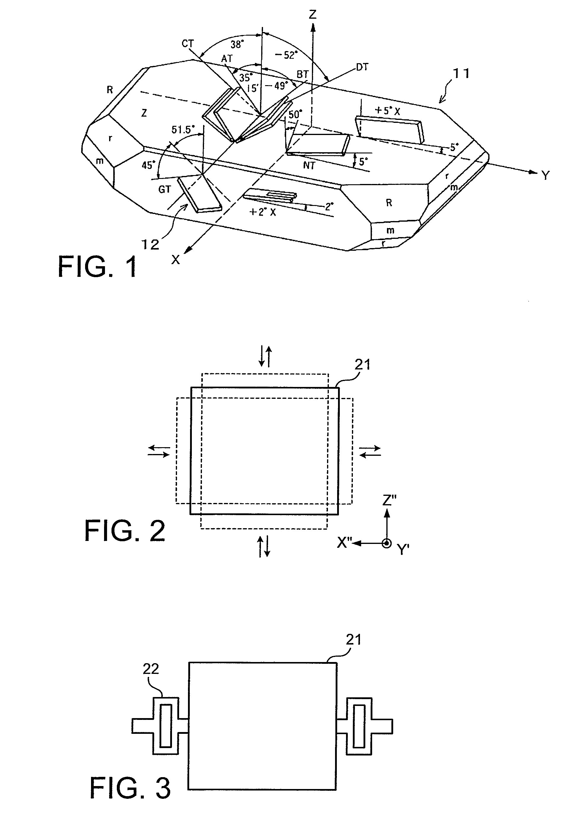
[0029]Elliptical crystal plate 31 has a configuration in which the plate surface is orthogonal to a Y′-axis in a GT-cut; the major axis of the ellipse coincides with an X″-axis in the GT-cut; and the minor axis of the ellipse coincides with a Z″-axis. As a result, crystal plate 31 has, as a vibration mode, a width-length extensional coupling vibration mode which is a coupling of a longitudinal vibration mode in an X″-axis direction and a longitudinal vibration mode in a Z″-axis direction and which allows alternate expansion and contraction in the X″-axis direction and the Z″-axis direction, as with crystal plate 21 illustrated in FIG. 2. Referring to FIG. 4, the outline of crystal plate 31 displaced by ...

second embodiment

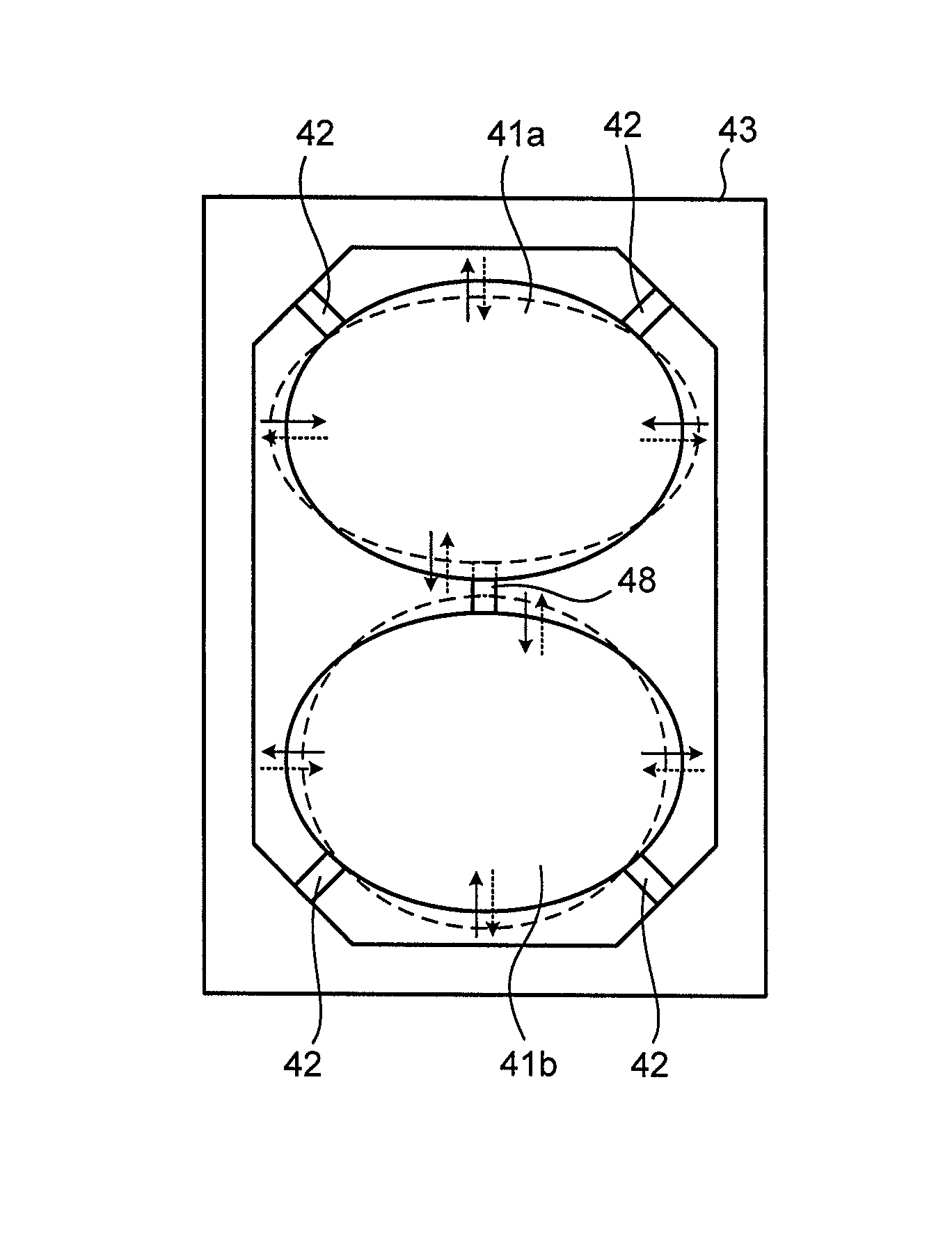
[0047]The GT-cut crystal resonator shown in FIGS. 9A to 9C has two pieces of GT-cut crystal plates 41a and 41b each having a elliptical shape, each of which is similar to one shown in FIG. 4. The crystal resonator has a configuration in which crystal plates 41a and 41b are held in an opening of frame 43. The directions of a minor axis and a major axis of each of crystal plates 41a and 41b coincide with vibration directions of two longitudinal vibration modes in a quartz crystal of the GT-cut, respectively. The vibration directions are orthogonal to each other. The outer shapes of crystal plates 41a and 41b are identical to each other, and both crystal plates 41a and 41b have thus an identical resonance frequency in the vibration mode of the GT-cut.

[0048]Each of crystal plates 41a and 41b is supported by two rod-shaped support portions 42 extending from the inner wall of frame 43. Two support portions 42 for each crystal plate are mechanically connected to the corresponding crystal ...

third embodiment

[0057]Next, a GT-cut crystal resonator according to the present invention will be described.

[0058]Two crystal plates 41a and 41b are used to constitute a crystal resonator in the second embodiment. However, in the present invention, it is possible to use three or more GT-cut crystal plates to couple all the crystal plates into a single vibration mode by iteratively making mechanical coupling between two adjacent crystal plates.

[0059]The crystal resonator according to the third embodiment shown in FIG. 10 is similar to that shown in FIGS. 9A to 9C except that three crystal plates 41a to 41c are provided. Each of crystal plates 41a to 41c is connected to frame 43 by two rod-shaped support portions 42 which are provided for each crystal plate. Support portions 42 are connected to the corresponding crystal plate at the positions on an outer periphery of the crystal plate where a minimum vibration displacement is obtained. One end of the minor axis of crystal plate 41a is connected to on...


PUM


Abstract

A GT-cut crystal resonator that can be provided with a support portion having a small and simple configuration without adverse effect on vibration characteristics includes: a crystal plate formed in an elliptical shape with a major axis and a minor axis respectively corresponding to vibration directions of two longitudinal vibration modes orthogonal to each other in a GT-cut; and a support portion that supports the crystal plate, the support portion being connected to a position on an outer periphery of the crystal plate where a minimum vibration displacement is obtained when the two longitudinal vibration modes are coupled.

Description

BACKGROUND OF THE INVENTION[0001]1. Field of the Invention[0002]The present invention relates to a GT-cut quartz crystal resonator.[0003]2. Description of the Related Art[0004]Crystal resonators for use as a reference source for a frequency or time are classified into several types of “cut” depending on a crystallographic orientation obtained when a crystal plate or crystal blank, i.e., a vibrating plate constituting a crystal resonator, is cut out from a single crystal of quartz (see, for example, Hirofumi Kawashima, Koichi Hirama, Naoya Saito, and Mitsuaki Koyama, “Quartz Resonators and Devices”, Transactions of the Institute of Electronics, Information and Communication Engineers C-I, Vol. J82-C-I, No. 12, pp. 667 to 682, December 1999). An AT-cut and an SC-cut have been widely known as examples of such a “cut”. Among them, a GT-cut crystal blank has an excellent frequency-temperature characteristic and shows an extremely small change in resonance frequency when the ambient tempe...

Claims


Application Information

Patent Timeline
Patent Type & Authority Patents(United States)
IPC IPC(8): H01L41/053H01L41/09
CPCH03H9/02023H03H9/02157H03H9/0595H03H9/132H03H9/205H03H9/2436
Inventor YAMAGUCHI, TAKASHIYAMADA, HIROAKI
Owner NIHON DEMPA KOGYO CO LTD
Why Eureka
Try Eureka