Outboard motor

a technology for outboard motors and motor parts, applied in the direction of marine propulsion, vessel construction, water acting propulsive elements, etc., can solve the problems of increasing the complexity of outboard motors, difficult to manufacture cases with complicated shapes, and difficult to manufacture cases with a large dimension in the up-down direction, so as to prevent an increase in weight, facilitate manufacturing of cases, and small configuration

Pending Publication Date: 2022-06-23
YAMAHA MOTOR CO LTD
View PDF0 Cites 0 Cited by
  • Summary
  • Abstract
  • Description
  • Claims
  • Application Information

AI Technical Summary

Benefits of technology

[0007]Preferred embodiments of the present invention provide outboard motors that are each easily manufactured while providing a sufficient mechanical strength and preventing an increase in weight even when the case has a complicated or large-sized configuration.
[0009]With the outboard motor described above, the case is obtained by assembling together a plurality of case parts. As compared with the case that is made of a single part, the plurality of case parts each have a relatively simple and small configuration. Therefore, it is possible to relatively easily manufacture the case even when the case has a complicated or large configuration. The plurality of case parts include a first case part and a second case part that oppose each other in the direction perpendicular to the axis of the drive shaft. When the first case part and the second case part are assembled on top of each other, they need to have a flange, which leads to an increase in weight, but there is no need for such a flange. Therefore, with the outboard motor described above, even when the upper case has a complicated or large configuration, it is possible to prevent an increase in weight while providing a sufficient mechanical strength.
[0010]According to preferred embodiments of the present invention, it is possible to provide outboard motors that are each easily manufactured while providing a sufficient mechanical strength and preventing an increase in weight even when the case has a complicated or large-sized configuration.

Problems solved by technology

In recent years, outboard motors are becoming more and more complicated in structure.
With casting, however, it is necessary to ensure a draft, and it is difficult to manufacture cases with complicated shapes.
With casting, however, it is difficult to manufacture a case having a large dimension in the up-down direction.
This, however, results in a problem that the upper and lower case parts each need to have a flange for the assembly, thereby increasing the weight of the case.

Method used


Image

  • Outboard motor
  • Outboard motor
  • Outboard motor

Examples


first preferred embodiment

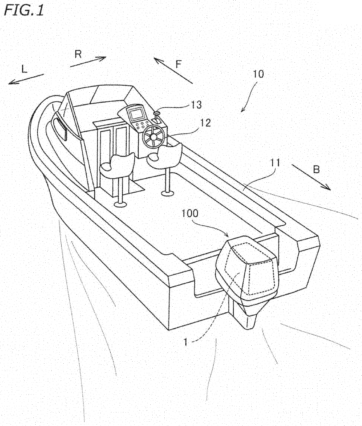
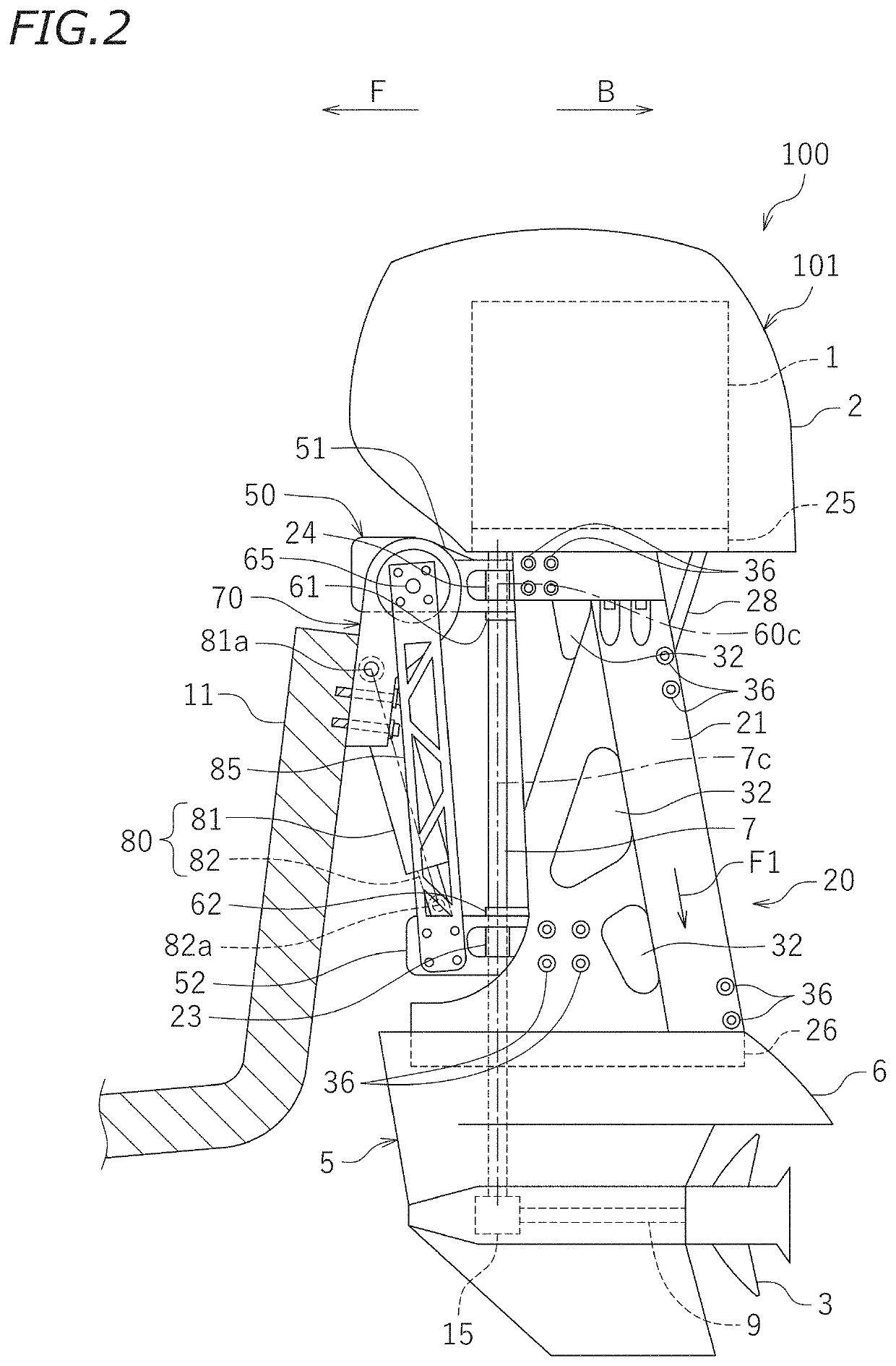
[0024]Preferred embodiments of the present invention will now be described with reference to the drawings. FIG. 1 shows a watercraft 10 including an outboard motor 100 according to the present preferred embodiment. The terms front, rear, left, and right, as used in the description below, refers to these directions as viewed facing the forward direction of the watercraft 10, while an axis 7c of a drive shaft 7 to be described below extends vertically and the outboard motor 100 is not inclined left and right relative to a hull 11. The designations F, B, L, and R, as used in the figures, refer to front, rear, left, and right, respectively.

[0025]The watercraft 10 includes the hull 11, a steering wheel 12, a remote controller 13, and the outboard motor 100. The outboard motor 100 is attached to the rear portion of the hull 11.

[0026]The steering wheel 12 steers the hull 11. As the passenger of the watercraft 10 operates the steering wheel 12, the outboard motor 100 rotates leftward or rig...

second preferred embodiment

[0069]The outboard motor 100 according to the second preferred embodiment of the present invention is similar to the outboard motor 100 according to the first preferred embodiment, with a change made to the configuration of the upper case 20. In the following description, like elements to those of the first preferred embodiment will be denoted by like reference signs, and will not be further described below.

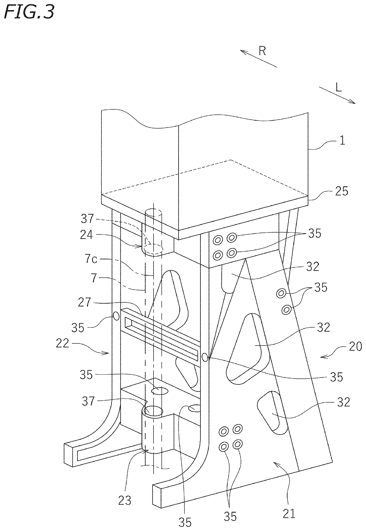
[0070]FIG. 8 is a perspective view showing the upper case 20 of the outboard motor 100 according to the second preferred embodiment. As in the first preferred embodiment, the upper case 20 is obtained by assembling together the first case part 21, the second case part 22, the third case part 23, the fourth case part 24, the upper plate part 25, and the lower plate part 26. Although not shown in the figure, the engine 1 is attached to the upper plate part 25, and the propulsion unit 5 is attached to the lower plate part 26.

[0071]The configuration of the first case part 21 and the ...


PUM


Abstract

An outboard motor includes an upper case located between an engine and a propulsion unit. The upper case includes case parts that are separate from each other and assembled together. The case parts include a first case part and a second case part opposing each other in a direction perpendicular or substantially perpendicular to an axis of a drive shaft.

Description

CROSS REFERENCE TO RELATED APPLICATIONS[0001]This application claims the benefit of priority to Japanese Patent Application No. 2020-212111 filed on Dec. 22, 2020. The entire contents of this application are hereby incorporated herein by reference.BACKGROUND OF THE INVENTION1. Field of the Invention[0002]The present invention relates to an outboard motor.2. Description of the Related Art[0003]There are conventional outboard motors known in the art that include a propulsion unit having a propeller, an engine that drives the propulsion unit, and a drive shaft that transmits the power of the engine to the propulsion unit (see, for example, JP A 2009-160970). The engine is arranged upward of the propulsion unit and is covered by a cover. A case is provided between the engine and the propulsion unit. The engine is secured to an upper portion of the case, and the propulsion unit is secured to a lower portion of the case. The engine and the propulsion unit are supported on the case. The dr...

Claims


Application Information

Patent Timeline
Patent Type & Authority Applications(United States)
IPC IPC(8): B63H20/32B63H23/34B63H20/02B63H20/12B63H20/10
CPCB63H20/32B63H23/34B63H20/10B63H20/12B63H20/02B63H20/08B63H20/14B63H20/002
Inventor MIZUTANI, MAKOTOHAGI, TOMOHIROYAMANOUCHI, MOTOSUMI
Owner YAMAHA MOTOR CO LTD
Why Eureka
Try Eureka