Fiber laser beam processing apparatus

a processing apparatus and fiber laser technology, applied in the field of fiber laser beam processing apparatus, can solve the problems of low optical coupling efficiency between excitation ld and dcf, poor beam quality concerning beam mode and convergence, and difficult obtaining high-output fiber laser beams using dcf lasers, etc., to achieve excellent convergence onto optical fiber for transmission, high-precision and high-efficiency fiber transmission, and stable injection numerical aperture and irradiation na

Inactive Publication Date: 2008-09-30
MIYACHI TECHNOS CORP
View PDF2 Cites 0 Cited by
  • Summary
  • Abstract
  • Description
  • Claims
  • Application Information

AI Technical Summary

Benefits of technology

[0008]The present invention was conceived in view of the above problems of the above conventional technique and the object thereof is to provide a fiber laser beam processing apparatus that mounts thereon a fiber laser that has a simple and small configuration and also has excellent maintainability and, in addition, a high output fiber laser beam suitable for laser beam processing can be easily obtained therefrom.
[0010]To optically pump the optical fiber for oscillation, the present invention employs an end-face excitation scheme with which simplification and downsizing of the excitation unit can be facilitated and the maintainability thereof is excellent. That is, the excitation beam from the excitation light source is condensed and injected onto the end face of the optical fiber for oscillation through the optical lens. In the optical fiber for oscillation, the excitation beam propagates in the clad in the axial direction repeating total reflection on the interface between the clad and the air layer. In the end-face excitation scheme, the maximum of the incident angle or the numerical aperture of the fiber for oscillation to receive the excitation beam is defined by the refractive index of the clad and the refractive index of the material surrounding the clad and, as the difference between the indexes becomes relatively larger, the numerical aperture becomes larger and the range of the incident angle at which the excitation beam can enter the end face of the clad becomes wider. The present invention employs a configuration of surrounding the clad with the air layer having the minimum refractive index and, thereby, a significant increase of the numerical aperture for the excitation beam can be facilitated and the excitation beam can be supplied to the optical fiber for oscillation in high efficiency coupling. Thereby, in the end-face excitation scheme, an increase of the output of the fiber laster beam can be easily and simply realized and desired laser beam welding processing can be executed excellently.
[0016]According to another preferred aspect, the fiber laser beam generated by the optical fiber for oscillation is transmitted to a laser beam irradiating unit through an optical fiber for transmission. In such a configuration, the beam mode and the laser output of the fiber laser beam are both stable and, therefore, the convergence onto the optical fiber for transmission is excellent and the injection numerical aperture (NA) and the irradiation NA are stable. Therefore, high-precision and high-efficiency fiber transmission is enabled and the quality of remote laser beam processing can be improved. In addition, the optical fiber for oscillation or the fiber laser oscillator can be placed away from a processing site and, therefore, the fiber laser oscillator can be protected against disturbances generated at the processing site such as vibrations, heat, ambient light, etc.
[0017]According to the fiber laser beam processing apparatus of the present invention, due to the above configuration and actions, a high-output fiber laser beam that is excellent in maintainability and suitable for laser beam processing can be easily obtained by a simple and small configuration.

Problems solved by technology

However, an LD beam has a poor beam quality concerning the beam mode and convergence thereof.
Therefore, a DCF laser of the LD end-face excitation scheme in the conventional fiber laser beam processing apparatus has a low optical coupling efficiency between the excitation LD and the DCF and, as a result, obtaining a high output fiber laser beam is difficult using the DCF laser.
On the contrary, an excitation unit (the optical guide and the LD for excitation) is complicated and bulky.
In addition, because the unit is physically integrally coupled to the optical fiber for oscillation, a problem has arisen that maintenance and repairing of components therein (especially the LD for excitation) is difficult.

Method used


Image

  • Fiber laser beam processing apparatus
  • Fiber laser beam processing apparatus
  • Fiber laser beam processing apparatus

Examples


Embodiment Construction

[0024]Description will be given for a preferred embodiment of the present invention referring to the accompanying drawings.

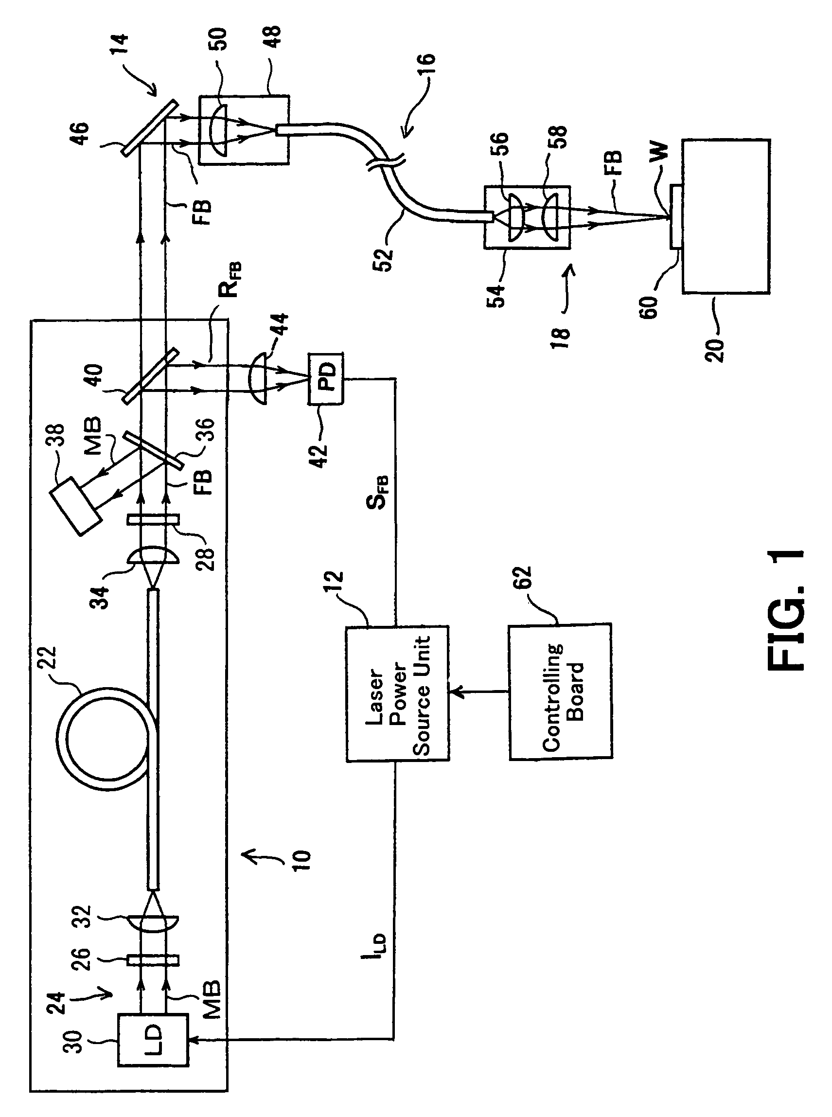
[0025]FIG. 1 depicts the configuration of a fiber laser beam processing apparatus in an embodiment of the present invention. The fiber laser beam processing apparatus is configured to include a fiber laser oscillator 10, a laser power source unit 12, a laser beam injecting unit 14, a fiber transmission system 16, a laser beam irradiating unit 18, a processing table 20, etc.

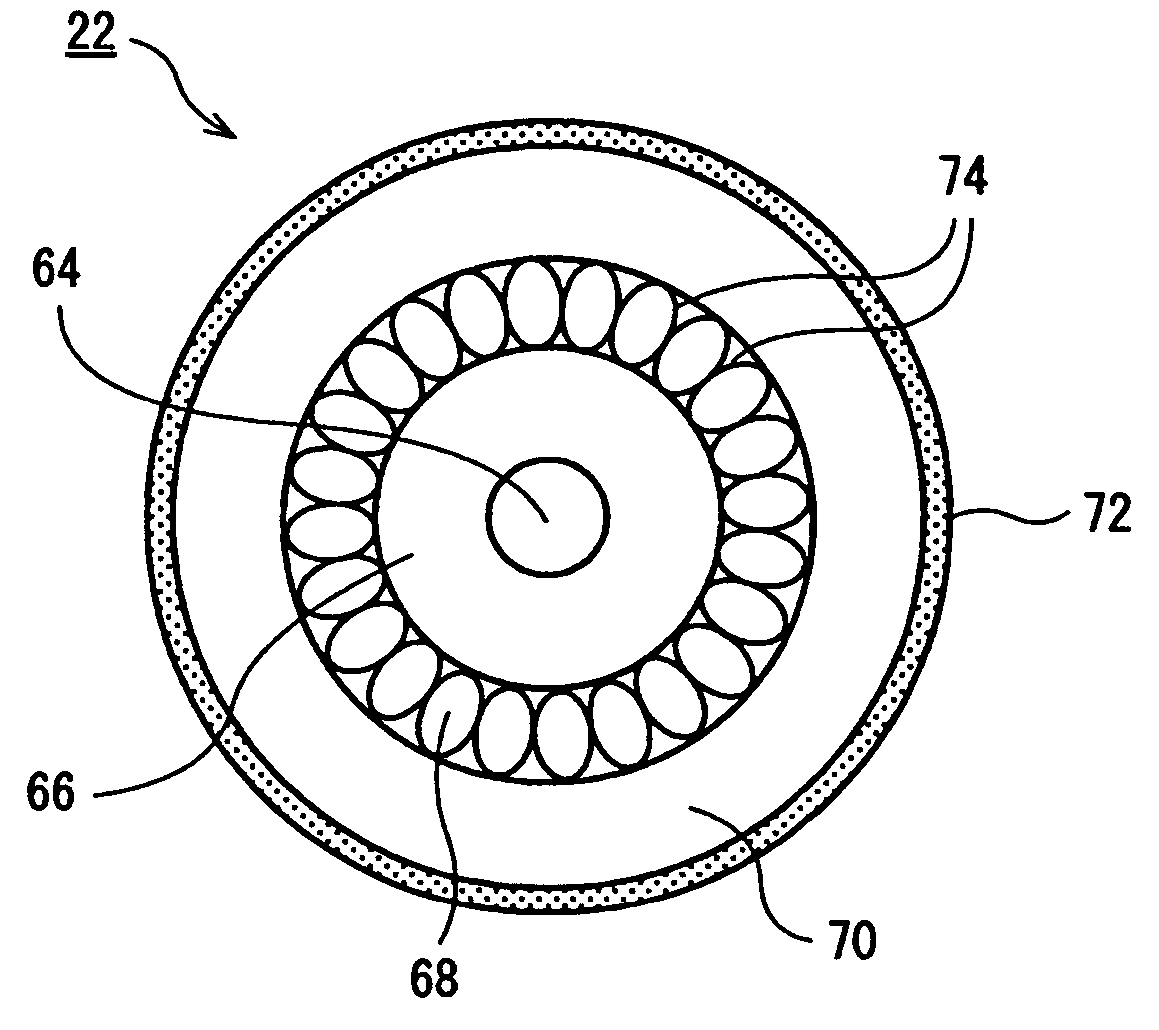
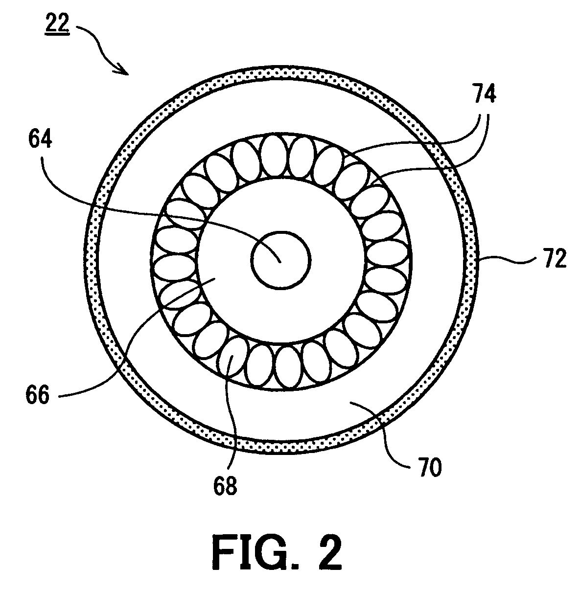
[0026]The fiber laser oscillator 10 includes an optical fiber for oscillation (hereinafter, “oscillating fiber”) 22, an electric optical pumping unit 24 that applies an excitation beam MB for optical pumping onto an end face of the oscillating fiber 22, and a pair of optical resonator mirrors 26 and 28 optically facing each other through the oscillating fiber 22.

[0027]The electric optical pumping unit 24 includes a laser diode (LD) 30 and an optical lens 32 for condensing the beam. The LD 30 i...


PUM

PropertyMeasurementUnit
diameteraaaaaaaaaa
wavelengthaaaaaaaaaa
laser poweraaaaaaaaaa

Abstract

The fiber laser beam processing apparatus includes a fiber laser oscillator, a laser power source unit, a laser injecting unit, a fiber transmission system, a laser beam irradiating unit, a processing table, etc. The fiber laser oscillator includes an optical fiber for oscillation, an electric optical pumping unit that applies an excitation beam for optical pumping onto an end face of the optical fiber for oscillation, and a pair of optical resonator mirrors optically facing each other through the optical fiber for oscillation. The optical fiber for oscillation includes a core extending on the central axis thereof, a clad surrounding the core, an air layer surrounding the clad, and a support surrounding and supporting the air layer.

Description

BACKGROUND OF THE INVENTION[0001]1. Field of the Invention[0002]The present invention relates to a fiber laser beam processing apparatus that executes laser beam processing using a fiber laser beam.[0003]2. Description of the Related Art[0004]Recently, a fiber laser beam processing apparatus has been practically used that executes desired laser beam processing by applying a laser beam generated by a fiber laser onto a work to be processed.[0005]A conventional fiber laser beam processing apparatus uses as an optical fiber for oscillation a double-clad fiber (DCF) having a two-layer clad structure including an inner clad and an outer clad; causes an excitation beam to propagate in the axial direction confining the beam in the inner clad by the total reflection on the interface between the clads; causes the beam to cross a core many times during the propagation; thereby, causes an excitation element in the core to be pumped; and takes out an oscillated beam or a fiber laser beam having...

Claims


Application Information

Patent Timeline
Patent Type & Authority Patents(United States)
IPC IPC(8): H01S3/30G02B6/02G02B6/42
CPCB23K26/0639B23K26/0643B23K26/0648B23K26/0665H01S3/067G02B6/02366H01S3/1312H01S3/06729H01S3/06741H01S3/094007H01S3/09415B23K26/064B23D17/04B26D7/26
Inventor MATSUDA, YASUSHISHIMADA, HIDENORINAKAYAMA, SHINICHI
Owner MIYACHI TECHNOS CORP
Why Eureka
Try Eureka