Laser shielding device

a laser shielding device and shielding technology, applied in the field of laser shielding devices, can solve the problems of lowering the degree of freedom in layout undesired, the structure of the laser shielding device is complicated, and the difficulty of sufficiently so as to achieve the effect of suppressing an increase in temperature of the object and simple and small configuration

Active Publication Date: 2021-01-05
HONDA MOTOR CO LTD
View PDF9 Cites 0 Cited by
  • Summary
  • Abstract
  • Description
  • Claims
  • Application Information

AI Technical Summary

Benefits of technology

[0005]A main object of the present invention is to provide a laser shielding device capable of, with a simple and small configuration, effectively suppressing an increase in temperature of the object to be shielded in a laser processing machine.
[0007]In the laser shielding device, it is preferable that, of the plurality of plates, an incident-side plate disposed on an incident side of the reflected light is larger in heat capacity compared to other plates disposed on the object side of the incident-side plate. By making the incident-side plate larger in heat capacity compared to other plates, it is possible to make the incident-side plate hardly increase the temperature even if the reflected light enters the incident-side plate. As a result, because the energy of heat radiation from the incident-side plate can be made small, it is possible to enhance the effect of the plurality of plates for suppressing the temperature of the object to be shielded from rising.
[0008]In the laser shielding device, it is preferable that the incident-side plate is larger in volume compared to other plates. By making the volume of the incident-side plate large, in other words, by making the mass large, it is possible to increase the heat capacity easily.
[0009]In the laser shielding device, it is preferable that, of the plurality of plates, an intermediate plate disposed between an incident side of the reflected light and a side adjacent to the object to be shielded is larger in thermal resistance compared to other plates. By making the intermediate plate larger in thermal resistance, it is possible to suppress the conduction of heat to the plate on the object side even if the heat conduction occurs from a plate on the incident side of the reflected light to the intermediate plate through a connecting portion or the like between the plurality of plates. Consequently, it is possible to satisfactorily suppress the radiation heat transfer from the plates to the object to be shielded and to effectively prevent the temperature of the object to be shielded from rising.
[0010]In the laser shielding device, it is preferable that the intermediate plate is smaller in cross-sectional area perpendicular to an extending direction compared to other plates. By reducing the cross-sectional area of the intermediate plate in a direction perpendicular to the extending direction, it is possible to easily make thermal resistance large in the extending direction of the intermediate plate.
[0011]In the laser shielding device, there may be further provided a connecting portion extending in a juxtaposed direction of the plurality of plates and integrally connecting the plurality of plates. In this case, because the plurality of plates can be connected integrally by one connecting portion, it is possible to further simplify the configuration of the laser shielding device.

Problems solved by technology

Therefore, it is difficult to sufficiently suppress an increase in temperature of the object.
A cooling structure for cooling the shielding plate may be provided in order to suppress the radiation heat transfer, but makes the structure of the laser shielding device complicated.
Further, if the shielding plate is disposed sufficiently away from the object to be shielded, the laser shielding device and the laser processing machine become large, lowering the degree of freedom in layout undesirably.

Method used


Image

  • Laser shielding device
  • Laser shielding device
  • Laser shielding device

Examples


Embodiment Construction

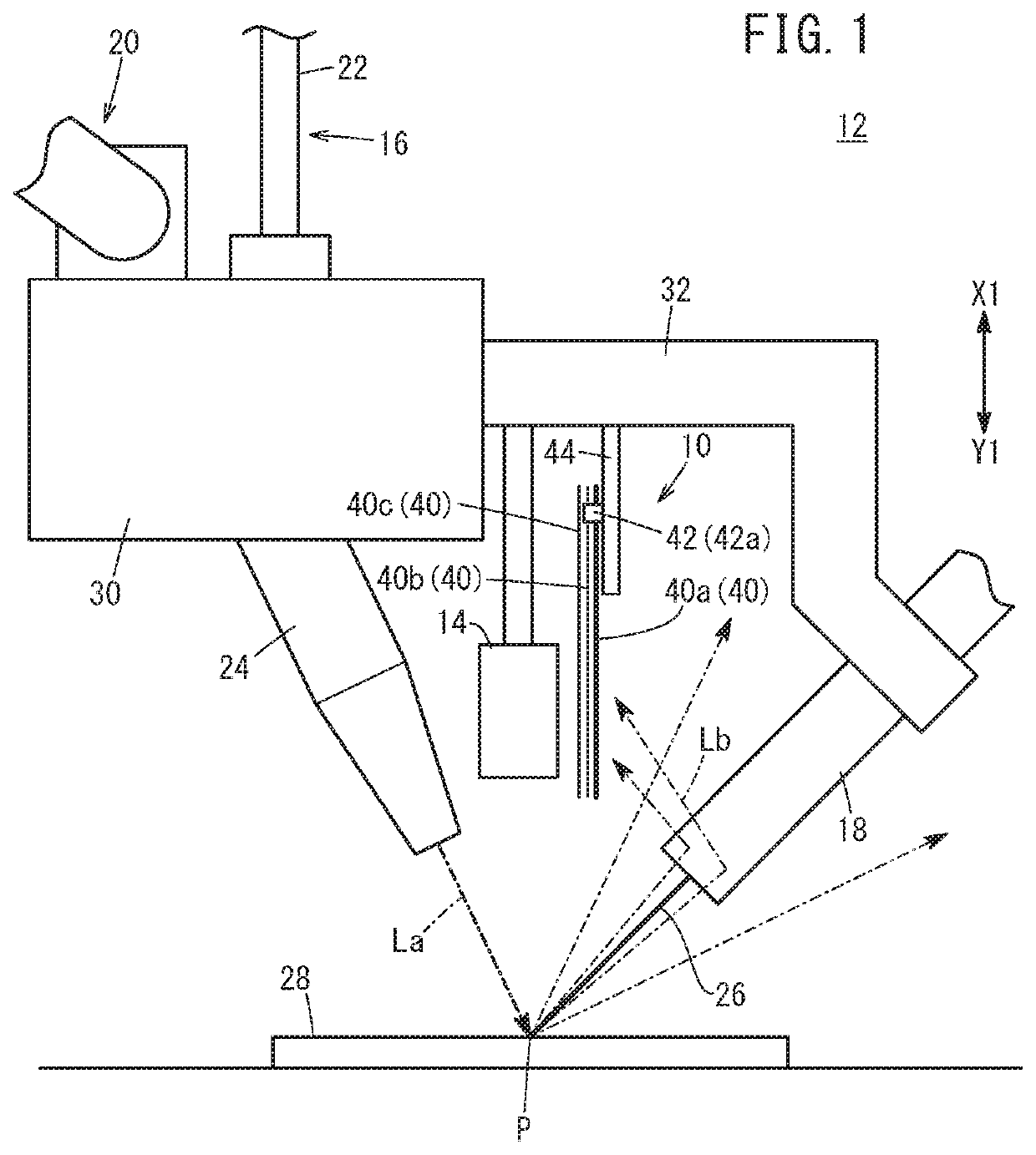
[0020]With reference to the accompanying drawings, a laser shielding device according to the present invention will be described in detail based on preferred embodiments.

[0021]In the laser shielding device, reflected light enters a plate disposed on the reflected light side of the plurality of plates interposed between the object to be shielded and the reflected light and is absorbed or reflected. Therefore, it is possible to prevent the reflected light from advancing toward the object to be shielded side beyond the plates, in other words, to shield the reflected light directed toward the object to be shielded. Further, even if the reflected light heats the plate on the reflected light side, it is possible to block the heat radiation directed from the heated plate toward the object to be shielded because the plurality of the plates are provided to be juxtaposed at an interval between the reflected light and the object to be shielded.

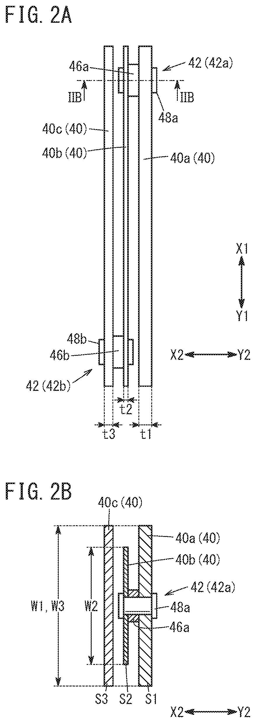
[0022]Further, the plurality of plates are juxtapo...


PUM

PropertyMeasurementUnit
thermal resistanceaaaaaaaaaa
heat capacityaaaaaaaaaa
volumeaaaaaaaaaa

Abstract

A laser shielding device interposed between the camera and the reflected light and is provided with a plurality of plates juxtaposed at an interval. Of the plurality of plates, an incident-side plate disposed on an incident side of the reflected light may be made larger in heat capacity compared to other plates disposed on the camera side of the incident-side plate.

Description

CROSS-REFERENCE TO RELATED APPLICATION[0001]This application is based upon and claims the benefit of priority from Japanese Patent Application No. 2017-137766 filed on Jul. 14, 2017, the contents of which are incorporated herein by reference.BACKGROUND OF THE INVENTIONField of the Invention[0002]The present invention relates to a laser shielding device for shielding reflected laser light directed toward an object to be shielded from laser light in a laser processing machine.Description of the Related Art[0003]For example, as disclosed in Japanese Laid-Open Utility Model Publication No. 04-039587, there has been known a laser shielding device for shielding reflected light directed toward an object to be shielded in order to prevent the reflected light of laser light irradiated from a laser irradiation unit from reaching the object to increase the temperature of the object to be shielded. The known laser shielding device is equipped with a plate of metallic shielding plate interposed ...

Claims


Application Information

Patent Timeline
Patent Type & Authority Patents(United States)
IPC IPC(8): G02B27/00B23K26/70B23K26/21G02B5/00B23K26/08B23K26/03B23K26/211
CPCB23K26/706B23K26/032B23K26/0869B23K26/21B23K26/211G02B5/003B23K26/702B23K26/703
Inventor KITAMURA, KENJI
Owner HONDA MOTOR CO LTD
Why Eureka
Try Eureka