Vehicle Lighting Device and LED Light Source Therefor

a technology of led light source and vehicle lighting, which is applied in the direction of semiconductor devices for light sources, discharge tubes luminescnet screens, lighting and heating apparatus, etc., can solve the problems of increased heat generation amount, large amount of heat generation, and marked degradation of phosphor, so as to achieve the restraint of the temperature rise in both the led light source and the phosphor layer

Inactive Publication Date: 2007-02-22
STANLEY ELECTRIC CO LTD
View PDF7 Cites 54 Cited by
  • Summary
  • Abstract
  • Description
  • Claims
  • Application Information

AI Technical Summary

Benefits of technology

[0061] The drive control section can be configured to adjust the drive current to flow in each LED chip of the LED light source at an optimal value based on the temperature in the vicinity of the LED light source detected by the temperature detecting element. The drive current supplied to each LED chip can be adjusted to the optimal value by the drive control section. Thus, a rise of temperature in both the LED light source and the phosphor layer can be restrained.

Problems solved by technology

Thus, a large amount of heat generation occurs.
In particular, the phosphor has a marked efficiency degradation caused by the temperature rise.
Thus, when efficiency is degraded due to the temperature rise, the energy not converted to light is converted to heat, which causes a further increase in the heat generation amount, resulting in a further rise of temperature and further degradation.
Now, according to the light source device disclosed in the JP'039 publication, it is not possible to perform sufficient radiation when the ambient temperature is high, and accordingly, it is not possible to efficiently radiate the heat generated by the LED chip.
Since the temperatures of the LED chip and the phosphor have not been measured accurately in real time, it has been difficult to drive the LED chip with an optimal drive current value.
As a result, the temperatures of the LED chip and the phosphor further rise, which results in a vicious circle of further efficiency degradation.
However, there may be cases in which the estimated temperature greatly differs from the actual temperature because the heat resistance of the package greatly differs among the packages of the same structure, depending on the junction conditions of the LED chip and the package.
Therefore, it has been difficult to detect the temperatures of the LED chip and the phosphor with accuracy.
Accordingly, when the LED chip is driven heat is generated in both the LED chip and then in the phosphor of the phosphor layer, causing a temperature rise in the LED chip and the phosphor layer.

Method used


Image

  • Vehicle Lighting Device and LED Light Source Therefor
  • Vehicle Lighting Device and LED Light Source Therefor
  • Vehicle Lighting Device and LED Light Source Therefor

Examples


Embodiment Construction

[0077] Hereinafter, some exemplary embodiments of the disclosed subject matter will be described in detail, referring to FIGS. 1 through 8.

[0078] Here, in the embodiments described below, a variety of technical features are included. However, the scope of the disclosed subject matter is not limited thereto.

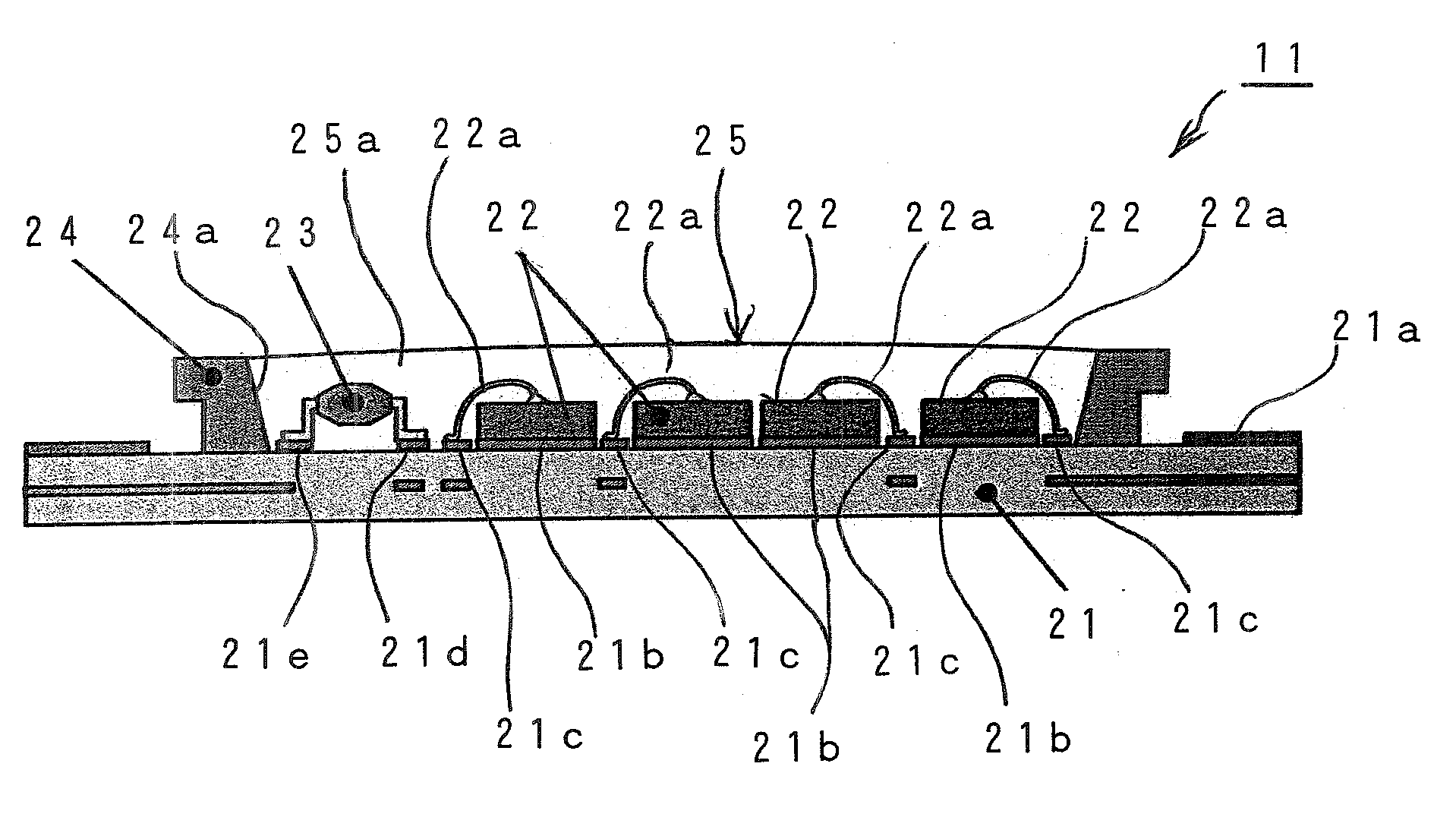
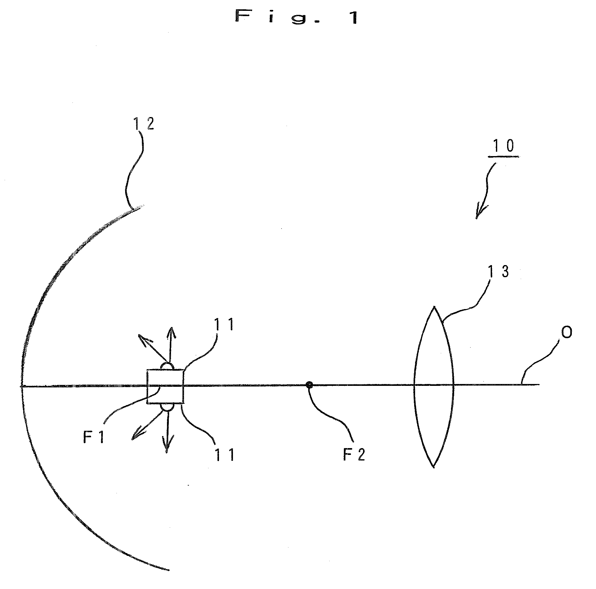
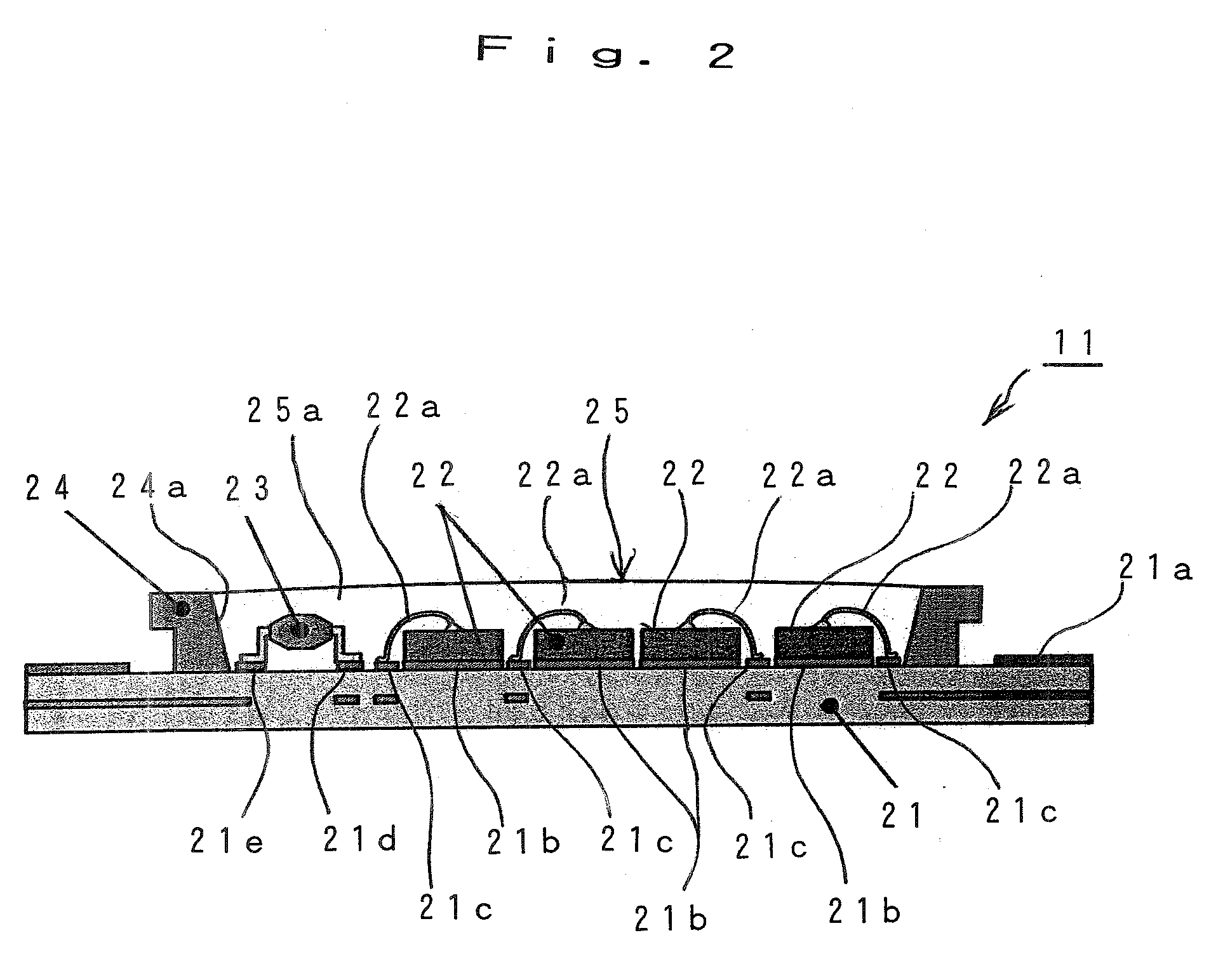
[0079]FIG. 1 shows the configuration of an embodiment of a vehicle lighting device made in accordance with principles of the disclosed subject matter. A vehicle lighting device 10 can include at least one LED light source 11 (in the figure, two LED light sources 11 are shown), a reflecting face 12 for reflecting the light from each LED light source 11 toward a forward direction along an optical axis O, and a projection lens 13 disposed in the forward direction of the reflecting face 12.

[0080] The LED light sources 11 can be disposed back to back along the optical axis O. As described later, a plurality of LED chips can be arranged perpendicular to the optical axis O in each LED...


PUM


Abstract

The disclosed subject matter aims to provide a vehicle lighting device and an LED light source therefore. Accurate temperature detection of an LED chip and associated phosphor can be monitored in real time. The LED light source can include at least one LED chip mounted on a base and a phosphor layer disposed adjacent the LED chip. A mixed particulate phosphor for generating fluorescence by means of the light emitted from the above LED chip can also be provided. The LED light source can be configured to output mixed color light containing the light from the LED chip and the fluorescence from the phosphor. The LED light source can also include a temperature detecting element located on the base and LED chip to detect the temperature on the periphery of the LED chip.

Description

[0001] This application claims the priority benefit under 35 U.S.C. §119 of Japanese Patent Application No. 2005-210484 filed on Jul. 20, 2005, which is hereby incorporated in its entirety by reference. BACKGROUND [0002] 1. Technical Field [0003] The disclosed subject matter relates to a light emitting diode (LED) light source for a vehicle lighting device, for example, to be used as a headlight, an auxiliary light, spotlight, traffic light, etc. for a vehicle or other application, and a vehicle lighting device using the above LED light source. [0004] 2. Related Art [0005] Conventionally, such an LED light source is configured, for example, as shown in FIG. 9. Namely, in FIG. 9, an LED light source 1 includes at least one LED chip 3 (in the case shown in the figure, four LED chips) placed on a base 2, a reflector 4 disposed on the base 2 so as to surround the LED chip(s) 3, and a phosphor layer 5 filled in a hollow 4a of the reflector 4. [0006] The above base 2 is formed of an insul...

Claims


Application Information

Patent Timeline
Patent Type & Authority Applications(United States)
IPC IPC(8): F21V9/00H01J1/62F21V29/00H01L33/50H01L33/56
CPCF21K9/00H01L25/167F21V23/0442F21Y2115/10F21V29/89H05B33/0821F21S41/147H01L2224/48227H01L2224/48465H01L2924/3025F21V23/003F21V29/86H01L2224/48091H01L2924/00014H01L2924/00H05B45/18F21S41/148H05B45/40
Inventor YATSUDA, YASUSHIHIRATA, HISAO
Owner STANLEY ELECTRIC CO LTD
Why Eureka
Try Eureka