Non-pneumatic wheel and wheel, suspension and tire used therein

a non-pneumatic, wheel technology, applied in the direction of springs/dampers, mechanical devices, transportation and packaging, etc., can solve the problems of vehicle damage, vehicle accidents, and expensive wheels, etc., to prevent tire blowout, reduce vehicle accidents, and prevent heat generation

Inactive Publication Date: 2011-10-13
CHON YOUNG ILL +4
View PDF15 Cites 55 Cited by
  • Summary
  • Abstract
  • Description
  • Claims
  • Application Information

AI Technical Summary

Benefits of technology

[0022]As described above, since the present invention has no air chamber and requires no air injection, it is possible to prevent tire blowout even when the tire is pierced by a sharp object such as a nail or glass shard so that the driving performance of the tire is unaffected. Therefore, it is possible to reduce vehicle accidents caused by blowout of a pneumatic tire during driving of a vehicle. In addition, it is possible to prevent generation of heat caused by hysteresis loss (due to friction by deformation) of the tire from repeated deformation due to variation in air pressure, thereby enhancing safety and remarkably increasing the lifespan of the tire.
[0023]Further, unlike operation mechanisms of the conventional pneumatic wheel, since shock is absorbed and attenuated and vibration is diminished through a separate suspension means for evenly distributing a load, it is possible to provide convenient and optimized driving performance, good ride comfort and good handling performance under various road conditions.
[0024]Furthermore, since the tire of the present invention is constituted by a tread and shoulders only, it is possible to prevent deformation, fatigue and heat storage of the tire even while the vehicle is rapidly driving, thereby preventing standing waves of the tire. In addition, heat can be readily discharged from a plurality of air vents passing through the wheel and tire to prevent an increase in temperature around a portion where braking is applied, and heat radiation from a brake drum or disc is improved to minimize generation of brake fade of the tire.
[0025]Further, since a suspension of the present invention is constituted by a plurality of resilient rings that rapidly and flexibly absorb and attenuate an external force, it is possible to provide good driving, road holding and handling performance, without modification of the shape and structure of the tread of the tire. In particular, it is possible to provide excellent safety and ride comfort at high speeds.
[0026]Furthermore, a gasket of the present invention minimizes transmission of friction and vibration noise to a vehicle body to reduce noise inside the vehicle.
[0027]In addition, since there is no need to store a spare tire in a trunk of the vehicle, it is possible to increase available space and reduce fuel consumption. Further, there is no need to individually adjust tire pressure. Since it is possible to reduce consumption of raw materials and cut down on waste, there are economic and environmental advantages.

Problems solved by technology

Therefore, if the tire is pierced or damaged by a sharp object such as a nail or glass shard, or loses too much air pressure due to some other cause during operation of the vehicle, the annular shape of the wheel is likely to be deformed and lose its function.
In more serious cases, a tire cord and rubber may be separated or cut causing the tire to be torn apart so that the vehicle becomes impossible to drive.
When the vehicle is driven with a flat or torn tire, the expensive wheel, suspension, and so on, of the vehicle may be damaged.
And at high speeds, serious accidents may occur.
However, compression, shearing stress and heat imparted to the tire due to repeated loads during driving cause fatigue fractures in the sidewalls.
In addition, the thick sidewalls, which aim at safety, reduce ride comfort.
However, since the tire employs plate-shaped spokes to absorb shock through yielding and reflecting movement, excessive noise and heat generated when driving the vehicle and relatively poor ride comfort in comparison with the pneumatic tire are obstacles to commercialization of the non-pneumatic tire.
However, since the link mechanisms and the spring members are formed as one integrated body, the tread can absorb only shock perpendicular to the road surface and does not properly absorb local shock.
However, it is impossible for the wheel to stably maintain an annular shape like the pneumatic wheel, and a part that contacts the road cannot be optimally subdivided.
Thus, noise due to shock is loud and ride comfort is reduced.
However, it is impossible to subdivide the tread according to function within the structure of the pneumatic wheel in which the tread is uniformly biased outward by air pressure.
Moreover, conventional wheels transmit friction and vibration noise from the tires through the vehicle body to the inside of the vehicle, thereby increasing noise inside the vehicle.

Method used


Image

  • Non-pneumatic wheel and wheel, suspension and tire used therein
  • Non-pneumatic wheel and wheel, suspension and tire used therein
  • Non-pneumatic wheel and wheel, suspension and tire used therein

Examples


Embodiment Construction

[0081]Exemplary embodiments of the present invention will now be described in detail with reference to the accompanying drawings.

[0082]Some terms used herein reflect functions and should be interpreted in light of the technical spirit of the present invention and common usage.

[0083]Further, when a description of functions or structures that are already known to those of skill in the art would detract from the clarity and concision of this disclosure, the description will be omitted.

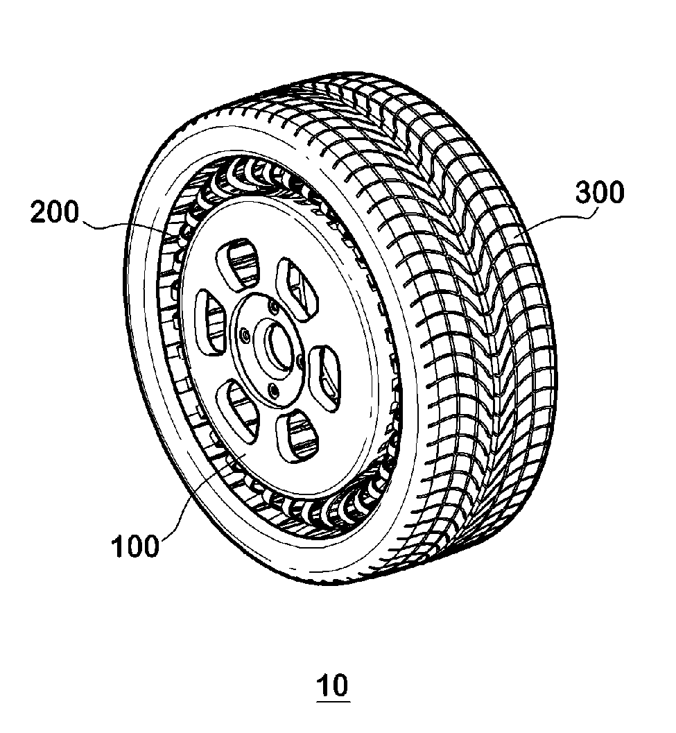
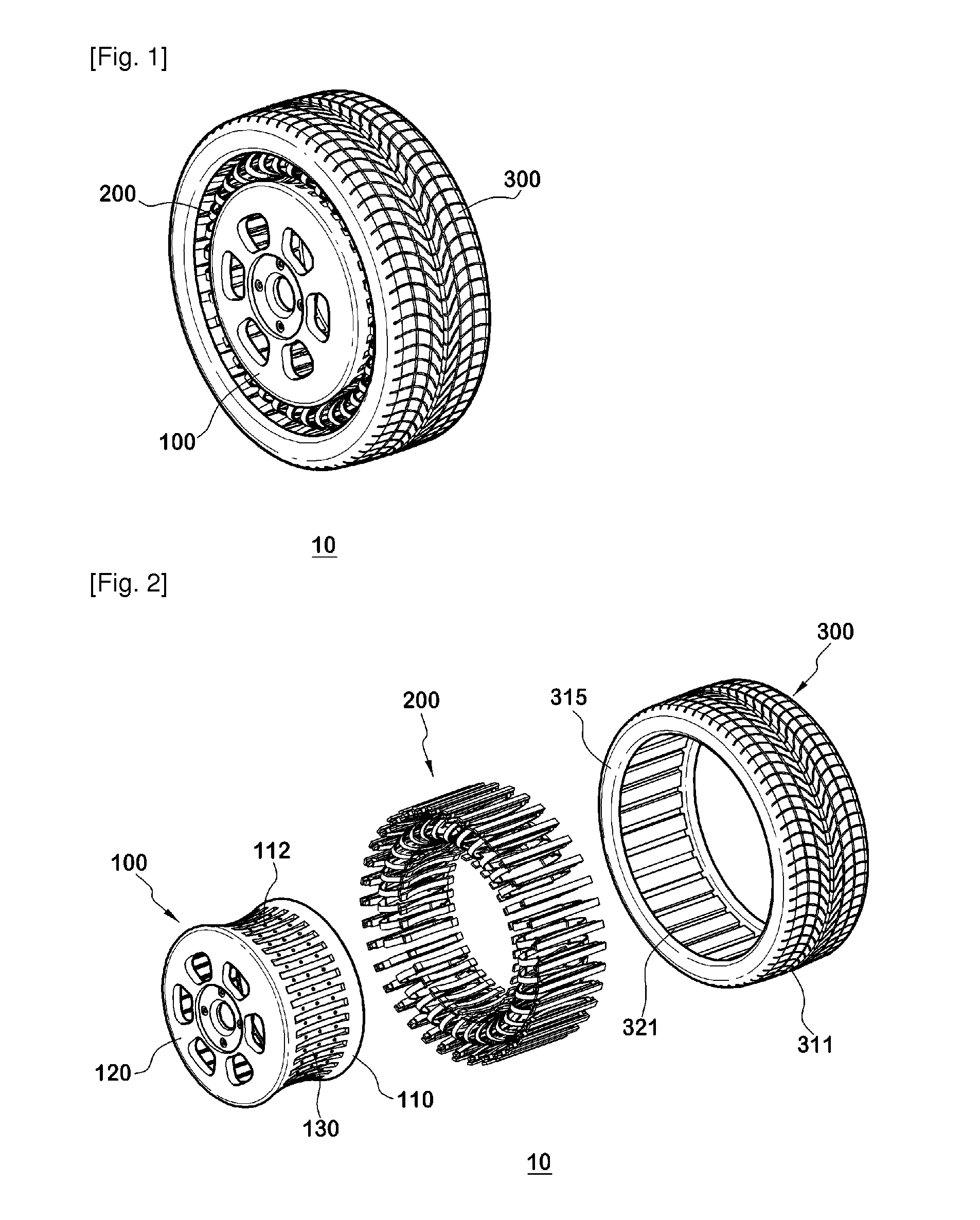
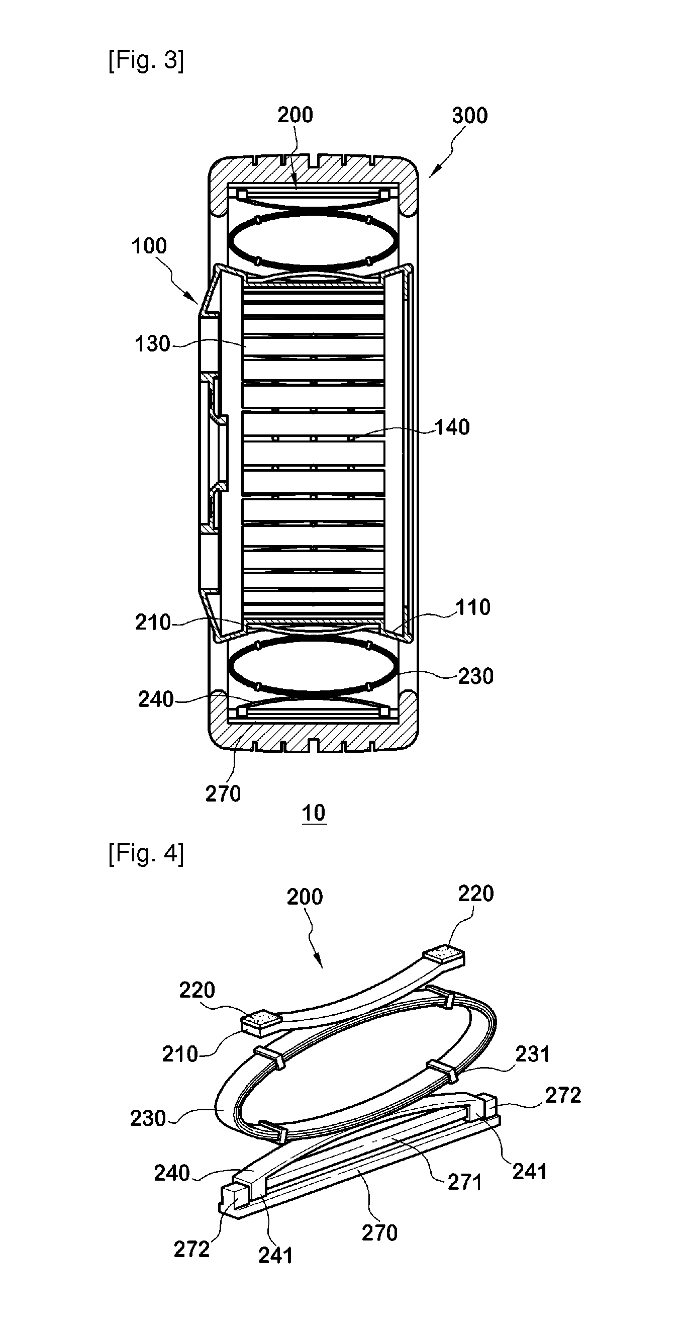
[0084]FIG. 1 is a perspective view of a non-pneumatic wheel in accordance with a first exemplary embodiment of the present invention, FIG. 2 is an exploded perspective view of FIG. 1, and FIG. 3 is an enlarged side cross-sectional view of FIG. 1. As shown in FIGS. 1 to 3, the non-pneumatic wheel 10 in accordance with a first exemplary embodiment of the present invention includes a wheel 100 coupled to an axle, a tire 300 in contact with a road surface, and a plurality of suspensions 200 installed between ...


PUM


Abstract

Provided is a non-pneumatic wheel (100) for a vehicle, and a wheel (100), suspension (200; 200-1), and tire (300) used therein that are capable of ensuring driving stability because there is no air chamber between a wheel (100) and a tire (300) to blowout. They are also capable of ensuring good road holding, preventing standing waves, reducing brake fade and cornering force, providing good handling and ride comfort, staying quiet when rolling, and are economical and environmentally friendly. The non-pneumatic wheel (100) includes a wheel (100), a shock absorbing member (220; 220-1) coupled to an outer periphery of the wheel (100) and absorbing or attenuating noise and vibration due to external shock, a plurality of resilient members (230; 230-1; 230-2) arranged around and coupled to an outer periphery of the shock absorbing member (220; 220-1) in a radial direction and having a plurality of resilient rings (230-1a) that are resiliently deformed in response to an external force, resilient links (240) respectively coupled to the resilient rings (230-1a) to evenly transmit external shock to the resilient rings (230-1a), rail plates (270) to which sliders (261) formed at both ends of the resilient links (240) are slidably coupled, and a tire (300) having a plurality of coupling grooves (321) formed along an inner periphery such that the rail plates (270) are inserted into the coupling grooves (321).

Description

TECHNICAL FIELD[0001]The present invention relates to a non-pneumatic wheel, and more particularly, to a non-pneumatic wheel for a vehicle, and a wheel, suspension, and tire used therein that are capable of ensuring driving stability because there is no air chamber between a wheel and a tire to blowout. They are also capable of ensuring good road holding, preventing standing waves, reducing brake fade and cornering force, providing good handling and ride comfort, staying quiet when rolling, and are economical and environmentally friendly.BACKGROUND ART[0002]Today's automobiles generally employ pneumatic wheels, in which a bead of a tire is sealed with a rim of the wheel to provide an inner space filled with air to a predetermined pressure such that the tire is expanded to form an annular shape appropriate for driving.[0003]The tire of a pneumatic wheel maintains the shape of the wheel and provides a drive function and ride comfort using filled air pressure. Therefore, if the tire is...

Claims


Application Information

Patent Timeline
Patent Type & Authority Applications(United States)
IPC IPC(8): B60C7/14F16F1/18B60B3/00B60C7/00B60B21/00
CPCB60C7/14Y10T152/10288B60B9/02B60C7/26B60C7/18B60C7/10B60C7/143B60C7/24B60B21/00B62D21/11
Inventor CHON, YOUNG-ILLLEE, SOON-JACHON, SUN-YOUNGCHON, SANG-HYUNCHON, SANG-WOOK
Owner CHON YOUNG ILL
Why Eureka
Try Eureka