Automobile brake cooling control device and control method
A control device and automobile braking technology, which is applied in the direction of brakes, cooling brakes, vehicle components, etc., can solve problems such as tire bursts, brake cooling failures, and high safety hazards, and achieve the effects of preventing tire bursts, simple structure, and low cost
- Summary
- Abstract
- Description
- Claims
- Application Information
AI Technical Summary
Problems solved by technology
Method used
Image
Examples
Embodiment 1
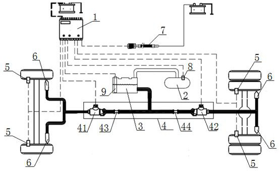
[0045] see figure 1 , an automobile brake cooling control device, including a body controller 1, an air storage tank 2, a water storage tank 3, a control valve assembly 4, four tire pressure sensors 5, and four water spraying devices 6, and the control valve assembly 4 includes a No. 4 water flow control valve 41, No. 2 water flow control valve 42, No. 1 check valve 43, and No. 2 check valve 44. The water port communicates with the water inlet of the No. 1 water flow control valve 41 through the No. 1 check valve 43, and communicates with the water inlet of the No. 2 water flow control valve 42 through the No. 2 check valve 44. The No. 1 water flow control The water outlet of the valve 41 communicates with the water inlets of the two water spray devices 6 respectively arranged on the two front tires of the vehicle, and the water outlet of the No. 2 water flow control valve 42 is respectively arranged on the two rear tires of the vehicle. The water inlets of the two water spra...
Embodiment 2
[0048] The difference with Example 1 is:
[0049] Described control device also comprises vehicle speed sensor 7, and the signal output terminal of described vehicle speed sensor 7 is connected with the signal input terminal of vehicle body controller 1, when vehicle body controller 1 detects that the vehicle speed from vehicle speed sensor 7 is zero, with The current tire pressure value of the tire pressure sensor 5 is used as the tire pressure reference value of the tire pressure sensor 5 when the vehicle runs next time.
Embodiment 3
[0051] The difference with Example 1 is:
[0052] The air storage tank 2 is provided with an air pressure sensor 8, the signal output end of the air pressure sensor 8 is connected with the signal input end of the body controller 1, when the body controller 1 detects that the air pressure value from the air pressure sensor 8 is lower than When the air pressure is at the minimum value, the No. 1 water flow control valve 41 and the No. 2 water flow control valve 42 are all closed.
PUM
 Abstract
Description
Claims
Application Information
 - R&D
- Intellectual Property
- Life Sciences
- Materials
- Tech Scout
- Unparalleled Data Quality
- Higher Quality Content
- 60% Fewer Hallucinations
Browse by: Latest US Patents, China's latest patents, Technical Efficacy Thesaurus, Application Domain, Technology Topic, Popular Technical Reports.
© 2025 PatSnap. All rights reserved.Legal|Privacy policy|Modern Slavery Act Transparency Statement|Sitemap|About US| Contact US: help@patsnap.com

