Posterior process dynamic spacer

a dynamic spacer and anterior process technology, applied in the direction of prosthesis, physical/chemical process catalysts, osteosynthesis devices, etc., can solve the problems of reducing the degree of extension of the back, causing pain, and possesses some limitations, so as to achieve the effect of gently limiting excessive extension

Active Publication Date: 2010-07-27
DEPUY SPINE INC (US)
View PDF73 Cites 66 Cited by
  • Summary
  • Abstract
  • Description
  • Claims
  • Application Information

AI Technical Summary

Benefits of technology

[0016]In a second embodiment, the implant has bases fastened to opposite sides of the same spinous process, and the bases are connected by a flexible cord. The cord is adapted to have a flexibility and resiliency such that, during extension (when the spinous processes move closer towards one another, the flexible cord provides a soft stop for the movement of the opposite spinous process, thereby gently limiting excessive extension.

Problems solved by technology

The leading cause of lower back pain arises from rupture or degeneration of lumbar intervertebral discs.
This condition (called “spinal stenosis”) produces a narrowing of the spinal canal and impingement of tissue upon the spinal cord, thereby producing pain.
Although the Zucherman device achieves spinal distraction, it nonetheless possesses some limitations.
First, it is a multi-piece design, and so is subject to wear and implantation complexity.
Second, since the Zuchermann central bodies have at least one integral wing, the clinician may encounter difficulty in sizing the central body independently of delivering the lateral wings.
Third, the expansive geometry of the disclosed devices may not lend itself to minimally invasive surgical techniques seeking to conserve muscle mass and soft tissue in the regions adjacent the spinous processes.

Method used


Image

  • Posterior process dynamic spacer
  • Posterior process dynamic spacer
  • Posterior process dynamic spacer

Examples


Embodiment Construction

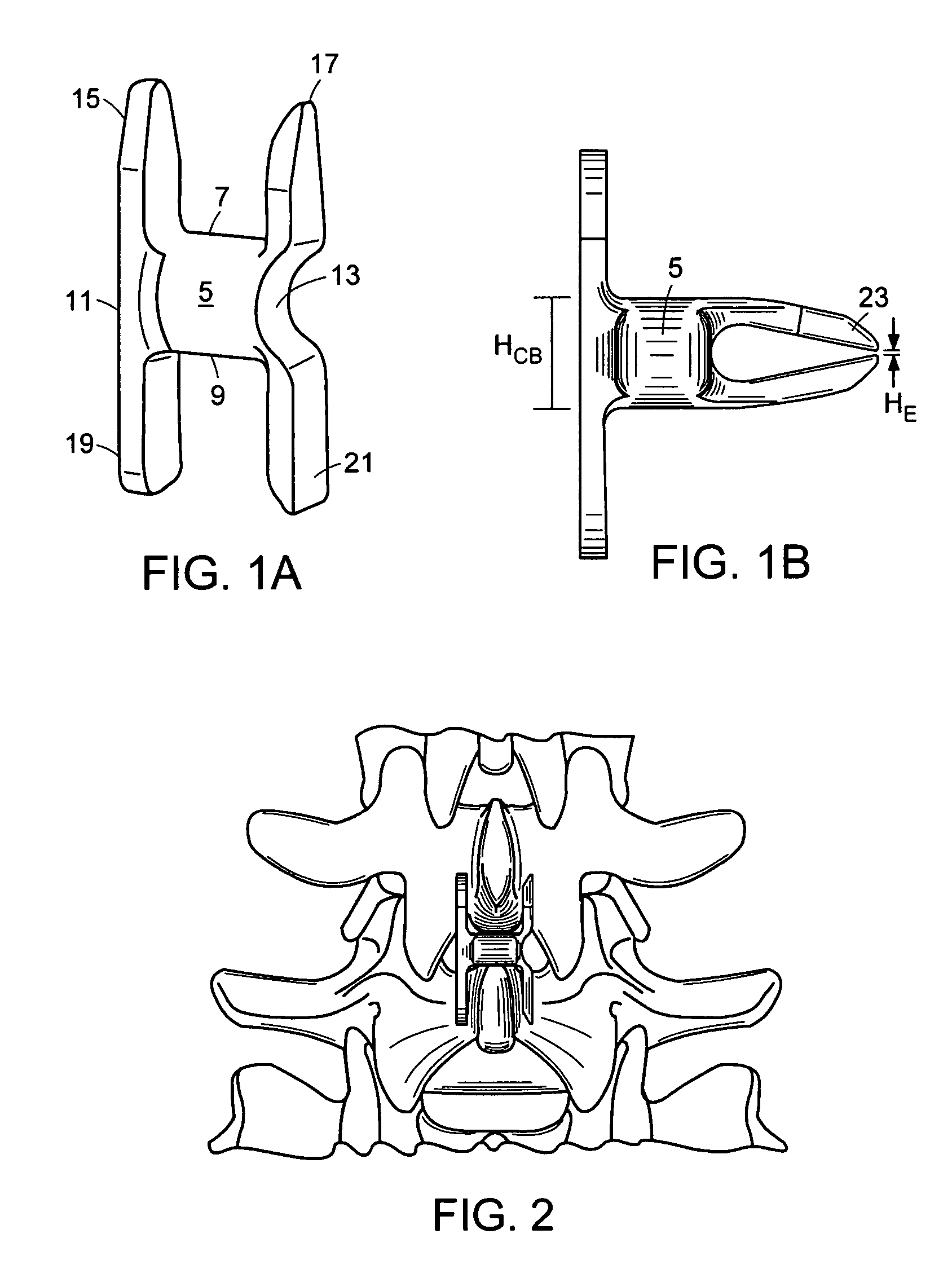
[0055]For the purposes of the present invention, the term “interspinous” refers to the volume located between two adjacent spinous processes of adjacent vertebrae. The terms “anterior” and “posterior” are used as they are normally used in spinal anatomy. P Accordingly, the “anterior” portion of the interspinous device is that portion rests relatively close to the spinal cord, while the “posterior” portion of the interspinous device is that portion rests relatively close to the skin on the patient's back. Now referring to FIG. 7, there is provided an anatomic “functional spinal unit” or FSU comprising an upper vertebrae having an upper vertebral body VU and an upper spinous process SPu, a lower vertebra having a lower vertebral body VL having a lower spinous process SPL. The vertebral bodies lies in the anterior A portion of the FSU, while the spinous processes lie in the posterior portion P of the FSU. Disposed between the vertebral bodies is a disc space DISC. Disposed between the ...


PUM

PropertyMeasurementUnit
angleaaaaaaaaaa
angleaaaaaaaaaa
thicknessaaaaaaaaaa

Abstract

An interspinous spacer having a memory metal extension.

Description

BACKGROUND OF THE INVENTION[0001]The leading cause of lower back pain arises from rupture or degeneration of lumbar intervertebral discs. Pain in the lower extremities is caused by the compression of spinal nerve roots by a bulging disc, while lower back pain is caused by collapse of the disc and by the adverse effects of articulation weight through a damaged, unstable vertebral joint.[0002]In some cases, when a patient having a collapsed disc moves in extension (e.g., leans backward), the posterior portion of the annulus fibrosus may further compress and extend into the spinal canal. This condition (called “spinal stenosis”) produces a narrowing of the spinal canal and impingement of tissue upon the spinal cord, thereby producing pain.[0003]There have been numerous attempts to provide relief for these afflictions by providing a spacer that inserts between adjacent spinous processes present in the posterior portion of the spinal column. In general, these interspinous implants are ad...

Claims


Application Information

Patent Timeline
Patent Type & Authority Patents(United States)
IPC IPC(8): A61F2/44A61B17/00A61B17/70B01J23/00C07D301/06C07D301/12
CPCA61B17/7062A61B17/7065A61B17/7068A61B2017/00867
Inventor HAWKINS, JOHN RILEYBORGSTROM, AMIEDUNBAR, JR., WILLIAM L.KWAK, SEUNGKYU DANIEL
Owner DEPUY SPINE INC (US)
Why Eureka
Try Eureka