Planar lighting device

a lighting device and planar technology, applied in the direction of lighting and heating equipment, semiconductor devices for light sources, instruments, etc., can solve the problems of limiting the extent to which the dimensions of the planar lighting device can be increased, the thickness and weight of the planar lighting device remain a challenge to overcome, and the limited distance that light can travel restricts the extent of the dimension increas

Active Publication Date: 2010-08-03
FUJIFILM CORP
View PDF9 Cites 62 Cited by
  • Summary
  • Abstract
  • Description
  • Claims
  • Application Information

AI Technical Summary

Problems solved by technology

While demands of still thinner backlight units are expected to grow in the future, achieving a further reduced thickness of say 10 mm or less with a backlight unit is difficult in view of uneven light amount distribution expected to accompany the direct illumination type.
Thus, reducing the thickness and the weight of the planar lighting device remains a challenge to be overcome.
Further, the shape as disclosed in JP 07-36037 A, JP 08-248233 A, JP 08-271739 A, and JP 11-153963 A having a tendency to decrease in thickness with the increasing distance from a position at which light from the light source is admitted or the flat plate shape also poses a problem that a limited distance that light is capable of traveling confines the extent to which the dimensions of the planar lighting device can be increased.
Although light having a higher brightness or illuminance may be emitted by using a light source having larger light emission faces to admit a greater amount of light into the light guide plate, there is a limit to the dimensions of each light emission face of the light source that can be used depending upon the shape of the light guide plate.

Method used


Image

  • Planar lighting device
  • Planar lighting device
  • Planar lighting device

Examples


Embodiment Construction

2.0 × 10−122.2 × 10140.30.033.5181.684◯Example 22.0 × 10−124.3 × 10140.30.026.2184.7149◯Example 32.0 × 10−128.6 × 10140.10.023.8682.882◯Example 41.1 × 10−101.5 × 10130.30.0083.9183.0105◯Example 51.1 × 10−102.0 × 10130.30.0074.9884.3142◯Example 61.1 × 10−103.5 × 10130.10.0072.8679.247◯Comparative example 12.0 × 10−122.2 × 10130.30.050.6629.151XComparative example 21.1 × 10−122.5 × 10120.30.010.9943.459XComparative example 34.8 × 10−188.6 × 10170.115.26.2684.8201XComparative example 44.8 × 10−181.7 × 10180.113.911.584.9225X

[0147]FIG. 6 illustrates a relationship between Φ·Np·LG·KC and light use efficiency, i.e., the ratio of light emitted through the light exit plane 30a to light incident on the light entrance planes.

[0148]Table 1 and FIG. 6 show that given Φ·Np·LG·KC of 1.1 or more, a high light use efficiency, specifically 50% or more, is achieved whereas given Φ·Np·LG·KC of 8.2 or less, illuminance unevenness can be held to 150% or less.

[0149]It is also shown that given KC of 0.005...


PUM


Abstract

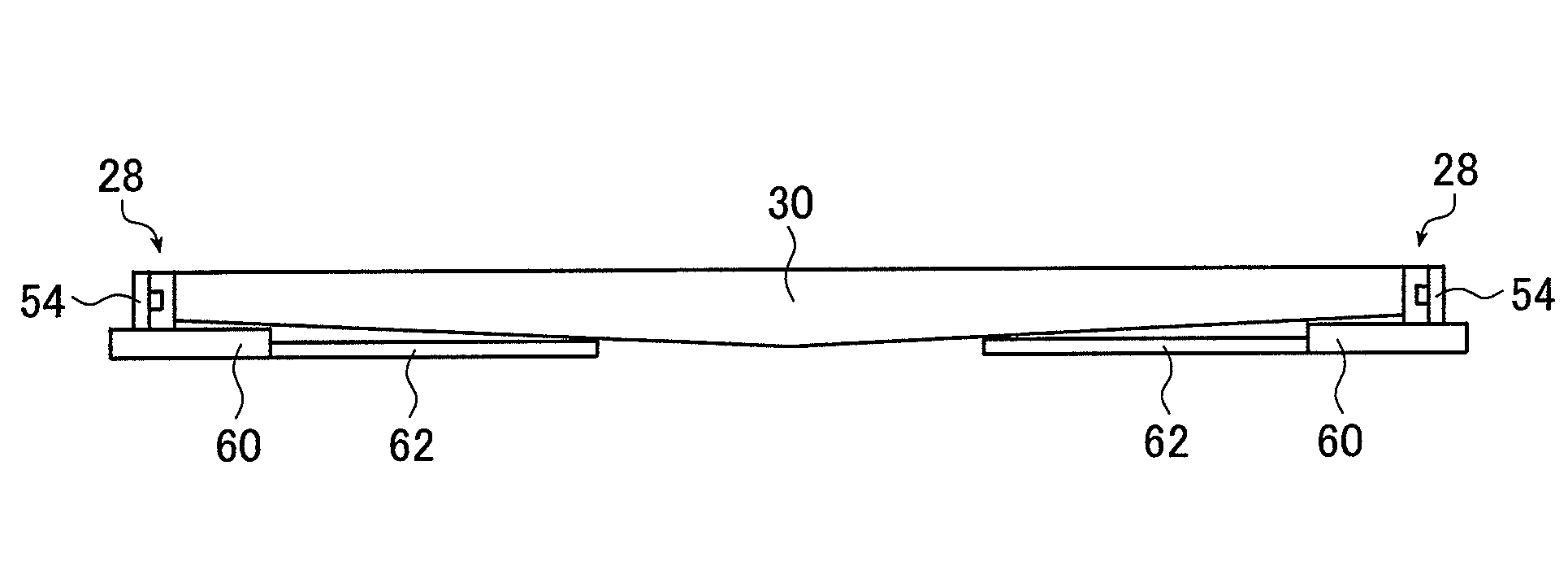
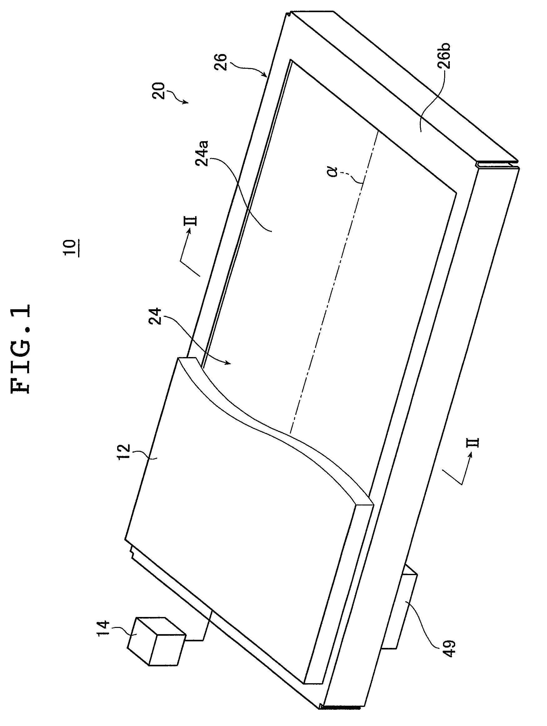
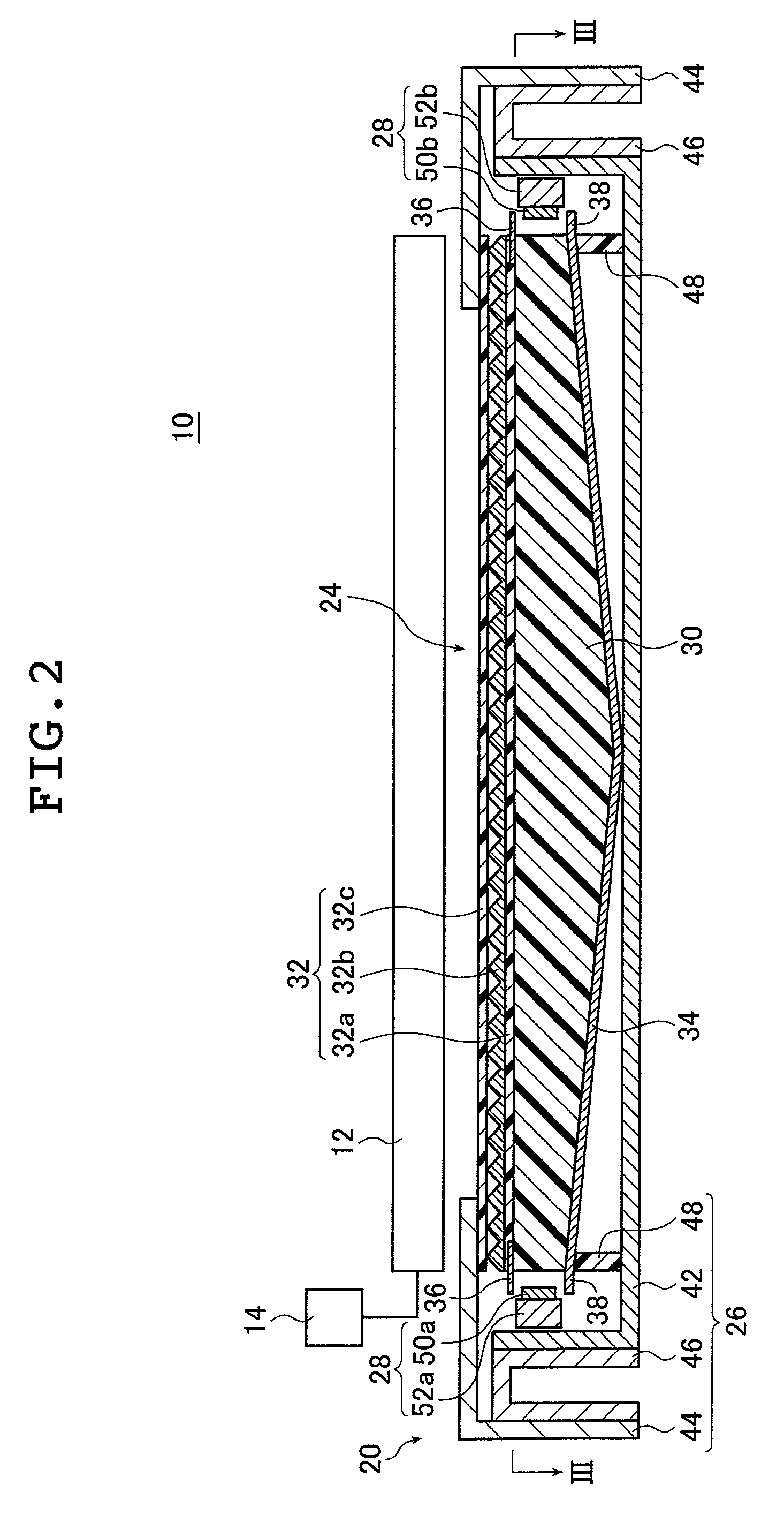
The planar lighting device includes a pair of light sources, a light guide plate and a housing. The light guide plate is disposed between the light sources and includes a light exit plane and a pair of opposite light entrance planes respectively provided opposite to the light sources. The planar lighting device thus configured features a heat dissipation structure whereby a heat sink is connected to each of the light sources and heat pipes are attached to the heat sink so as to extend toward the center of the housing. Disclosed is a thin and lightweight planar lighting device suitably used for a large display television or the like, capable of emitting illumination light free from brightness unevenness or with a reduced level of brightness unevenness, allowing increase of dimensions of the display area, and capable of optimally releasing heat generated by the light sources.

Description

[0001]The entire contents of literature cited in this specification are incorporated herein by reference.BACKGROUND OF THE INVENTION[0002]The present invention relates to a planar lighting device comprising light sources and a light guide plate for admitting light emitted by the light sources and emitting light through the light exit plane thereof. The inventive planar lighting device is used for indoor and outdoor illumination or as a backlight to illuminate the liquid crystal display panel used in liquid crystal display devices or a backlight used for advertising panels, advertising towers, advertising signs, and the like.[0003]Liquid crystal display devices use a backlight unit for radiating light from behind the liquid crystal display panel to illuminate the liquid crystal display panel. A backlight unit is configured using optical members such as a light guide plate for diffusing light emitted by an illumination light source to irradiate the liquid crystal display panel, a pris...

Claims


Application Information

Patent Timeline
Patent Type & Authority Patents(United States)
IPC IPC(8): F21V29/00
CPCF21V29/02F21V29/20G02B6/0073G02B6/0085F21Y2101/02G02B6/0021G02B6/0046G02B6/0068G02F1/133615G02B6/0053F21V29/51F21V29/763F21Y2115/10
Inventor IWASAKI, OSAMU
Owner FUJIFILM CORP
Why Eureka
Try Eureka