Jet exhaust noise reduction system and method

a technology of jet exhaust and noise reduction, applied in the direction of marine propulsion, vessel construction, aircraft navigation control, etc., can solve the problems of jet exhaust noise, jet exhaust noise is created, and the structure lack of streamwise vorticity to create bypass flow for interaction further upstream, etc., to achieve the effect of reducing jet noise emission

Active Publication Date: 2006-10-03
RTX CORP
View PDF27 Cites 31 Cited by
  • Summary
  • Abstract
  • Description
  • Claims
  • Application Information

AI Technical Summary

Benefits of technology

[0009]Another embodiment according to the invention is directed to a method for reducing jet noise emission from an internally mixed gas turbine engine. The method involves selectively aligning a circumferential distribution of an internally mixed flow vorticity field with a circumferentially distributed engine exhaust flow vorticity field at or near an exit plane of an exhaust nozzle of the engine. An aspect of the embodiment includes clocking a plurality of nozzle tabs with a corresponding plurality of mixer lobes. Another aspect is directed to orienting a plurality of nozzle tabs in such a manner that they protrude radially within a predetermined range in relation to the radial penetration of the mixer lobes.

Problems solved by technology

The generation of noise from turbulent jet exhaust is the dominant component of jet engine noise during aircraft takeoff.
This noise presents public and environmental concerns and the reduction of jet noise emission continues to be a challenging problem.
Jet exhaust noise is created by the turbulent mixing of high velocity engine gases that emanate from the rear of a modern gas turbine.
In large measure, it is the shearing forces between the high-velocity exhaust gases and the ambient air that produce the significant noise emission.
These techniques, while creating a vorticity field downstream of the tab, lack any structure to create bypass flow streamwise vorticity for interaction farther upstream.
The present inventors have discovered, however, that the mere combination of internal mixer and external exhaust shroud modifications, without proper consideration of their relative placement and orientation may actually increase jet exhaust noise.

Method used


Image

  • Jet exhaust noise reduction system and method
  • Jet exhaust noise reduction system and method
  • Jet exhaust noise reduction system and method

Examples


Embodiment Construction

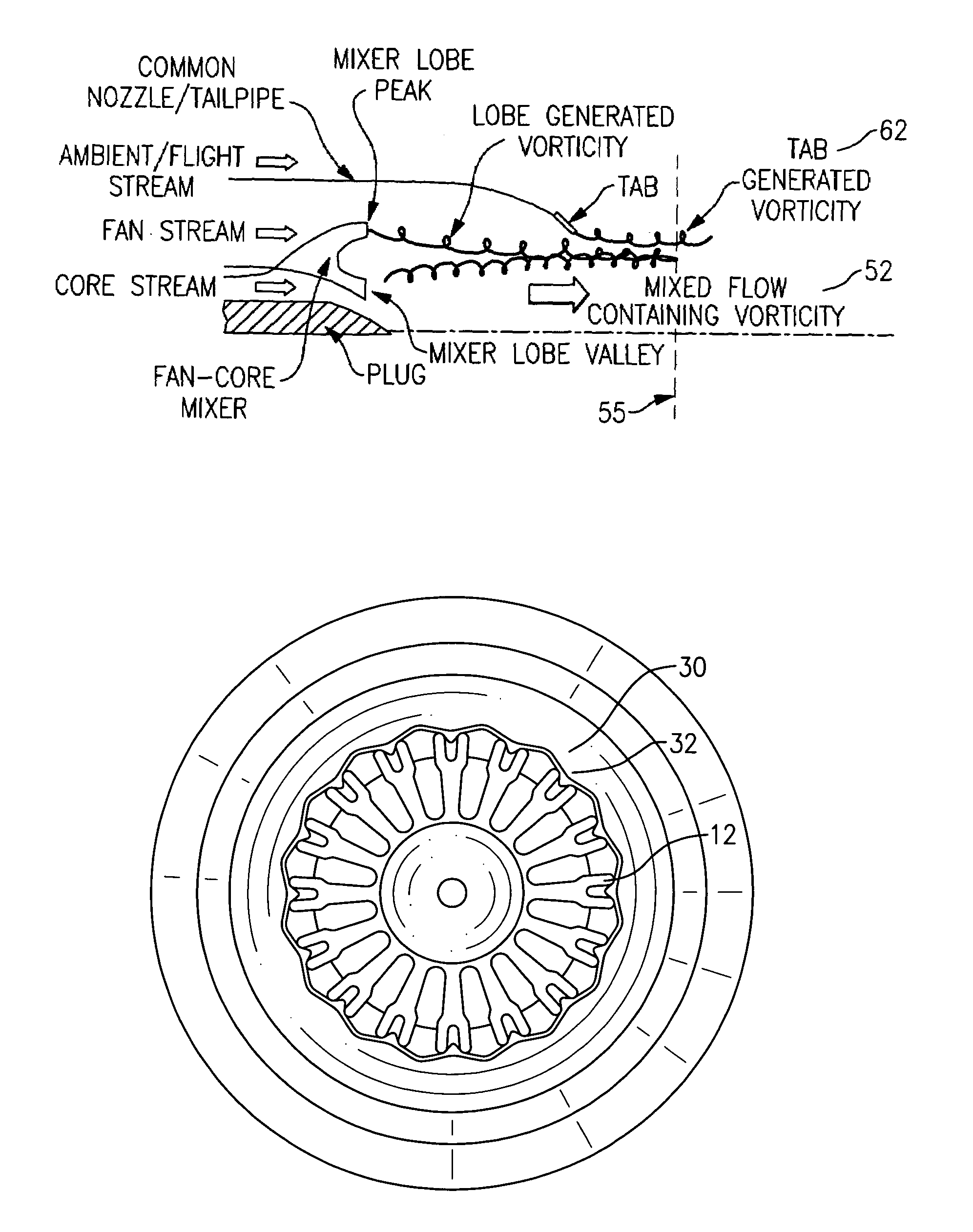
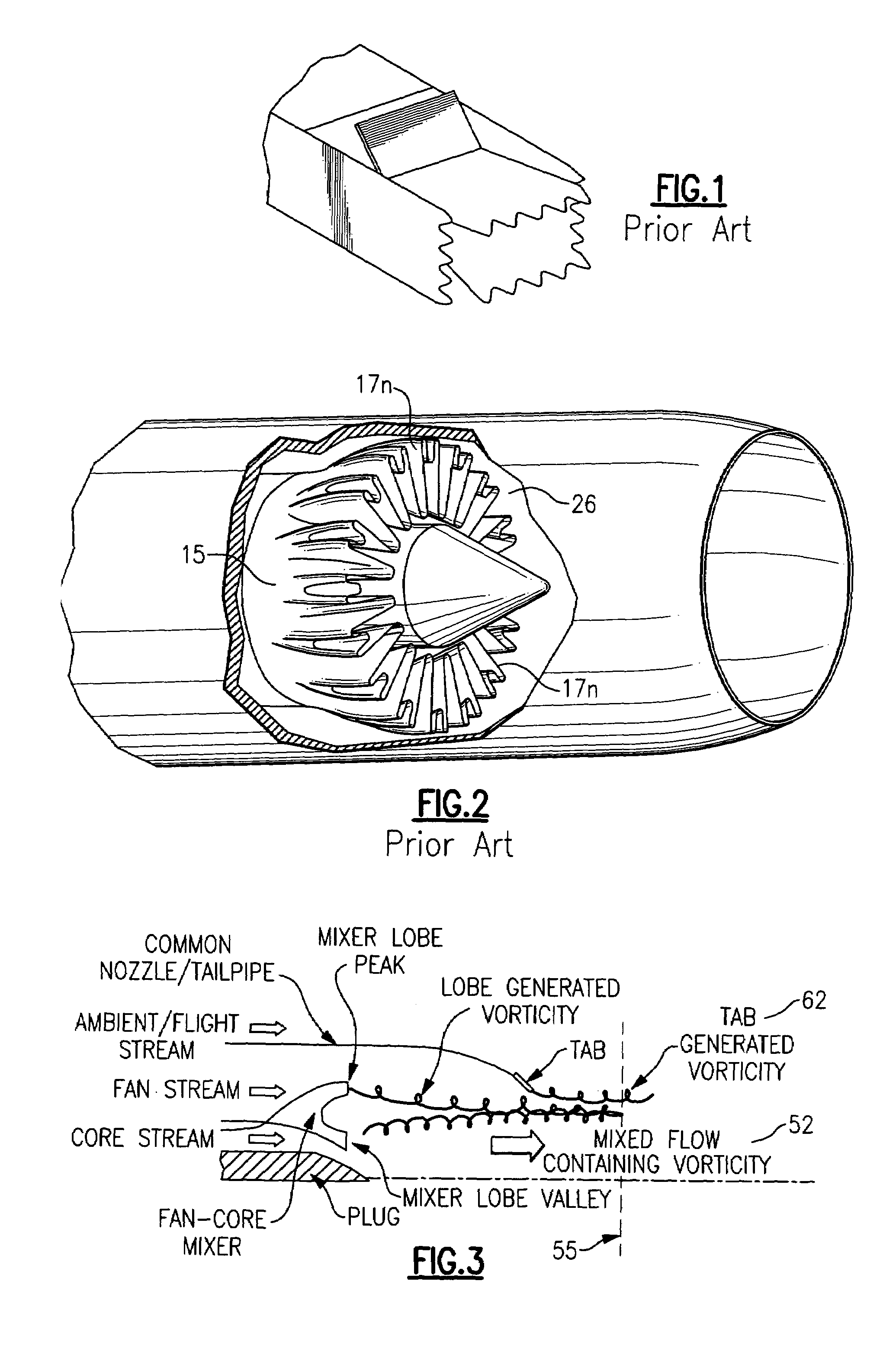
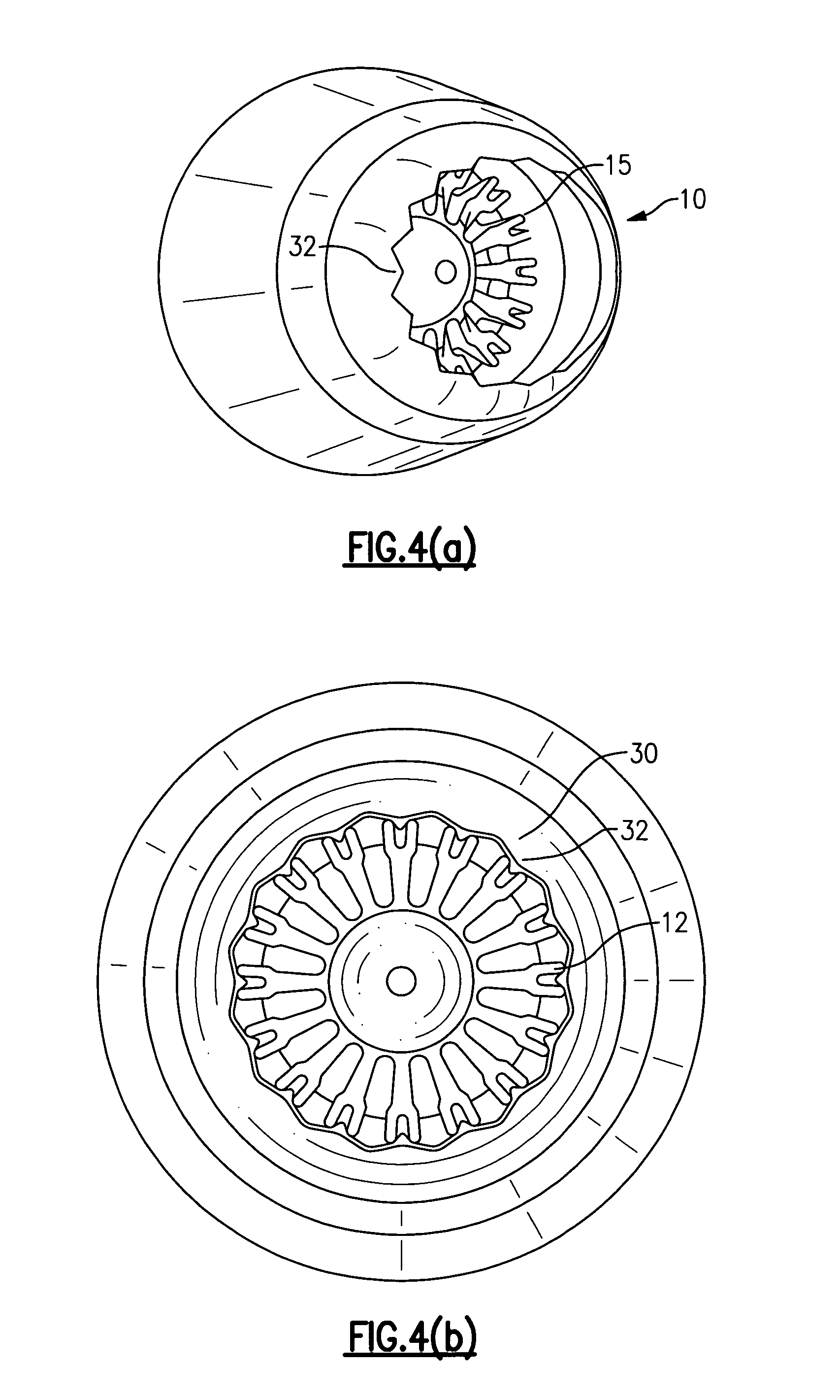
[0032]An embodiment of the invention is directed to a system 10 for reducing jet noise emission from an internally mixed gas turbine engine exhaust as illustrated by the photocopy views shown in FIGS. 4(a) and 4(b). The system includes a fan / core flow mixer 15 having a periodically configured series of mixer lobes 17n each having a major peak 20 and a major valley 22, as illustrated in FIG. 5 for a conventional single-lobe mixer 16, and for a double-lobe mixer 26 as illustrated in FIG. 2. The mixer 15 is in operational combination with a common flow nozzle 30 whose aft end circumferential edge 12 has been geometrically modified as shown in FIG. 4(a) and FIG. 9. With reference to FIG. 9, the geometrical modification is in the form of a series of tabs 32n each having a base region 33 (encompassing a tab base) and a tip end 34. According to the embodiment, the number of mixer lobes 17n is equal to the number of nozzle tabs 32n and there is a predetermined clocking relationship between ...


PUM


Abstract

A system for reducing jet noise emission from an internally mixed gas turbine engine exhaust, comprising a fan / core flow mixer having a plurality of mixer lobes and a common flow nozzle having an equal number of tabs located along a circumferential edge of an aft end of the nozzle. There is a predetermined clocking relationship between the plurality of mixer lobes and the plurality of nozzle tabs that results in reduced exhaust noise emission, most evident in the lower frequency range. A method for reducing jet noise emission from an internally mixed gas turbine engine exhaust comprises selectively aligning a circumferential distribution of a mixed flow vorticity field produced by a fan / core mixer with a circumferentially distributed exhaust flow vorticity field produced by a modified common flow nozzle at an exit plane of the engine exhaust.

Description

BACKGROUND OF THE INVENTION[0001]1. Field of the Invention[0002]Embodiments of the invention are generally directed to gas turbine engine noise reduction and, more particularly, to a tandem system including an internal mixer and an exhaust nozzle modification, and an associated method, for effective flow stream mixing to reduce jet noise emission.[0003]2. Description of Related Art[0004]The generation of noise from turbulent jet exhaust is the dominant component of jet engine noise during aircraft takeoff. This noise presents public and environmental concerns and the reduction of jet noise emission continues to be a challenging problem.[0005]Jet exhaust noise is created by the turbulent mixing of high velocity engine gases that emanate from the rear of a modern gas turbine. In large measure, it is the shearing forces between the high-velocity exhaust gases and the ambient air that produce the significant noise emission. Generally speaking, the jet noise generated by turbo fan engine...

Claims


Application Information

Patent Timeline
Patent Type & Authority Patents(United States)
IPC IPC(8): B63H11/00B64G9/00F02K9/00B64G99/00F02K1/34
CPCF02K1/386Y02T70/56Y02T70/50
Inventor SCHLINKER, ROBERTNARAYANAN, SATISHLORD, WESLEY K.KOHLENBERG, GREGORY A.REBA, RAMONSSIMONICH, JOHNSOTERIOU, MARIOS C.MAEDER, THIERRY
Owner RTX CORP
Why Eureka
Try Eureka