Multi-mode—multi-band direct conversion receiver with complex I and Q channel interference mitigation processing for cancellation of intermodulation products

a technology of intermodulation products and interference mitigation, applied in the direction of transmission noise suppression, transmission, electrical equipment, etc., can solve the problems of direct conversion, dc offset, implementation challenges,

Active Publication Date: 2010-08-10
SMITH FRANCIS J
View PDF5 Cites 61 Cited by
  • Summary
  • Abstract
  • Description
  • Claims
  • Application Information

AI Technical Summary

Problems solved by technology

Direct conversion, while it does have desirable attributes, does have implementation challenges.
Direct conversion receivers also have the problem of Direct Current (DC) offset which can be caused by self-mixing of the Local Oscillator (LO) caused by LO feed thru, which is at the carrier frequency, producing a DC term in the down converted signal.
The frequency planning for North America presents some unique systems engineering problems.
This presents a severe interference environment where different standards use different frequency assignments in the bands and can interfere with each other by creating intermodulation products by mixing with other signals in the band.
3G WCDMA will be more vulnerable because the band width is 3 times that of CDMA2000, and it may be subjected to multiple IMPs
As shown in FIG. 1, the blocking signals can be quite large and can limit the sensitivity and dynamic range of a mobile receiver.
CDMA is the most susceptible because it is a stationary (does not frequency hop) wideband signal and thus there is high probability that inter-mods generated in the receive band can fall inband of the signal of interest.
WCDMA may have the problem of multiple inter-mods falling inband.

Method used


Image

  • Multi-mode—multi-band direct conversion receiver with complex I and Q channel interference mitigation processing for cancellation of intermodulation products
  • Multi-mode—multi-band direct conversion receiver with complex I and Q channel interference mitigation processing for cancellation of intermodulation products
  • Multi-mode—multi-band direct conversion receiver with complex I and Q channel interference mitigation processing for cancellation of intermodulation products

Examples


Embodiment Construction

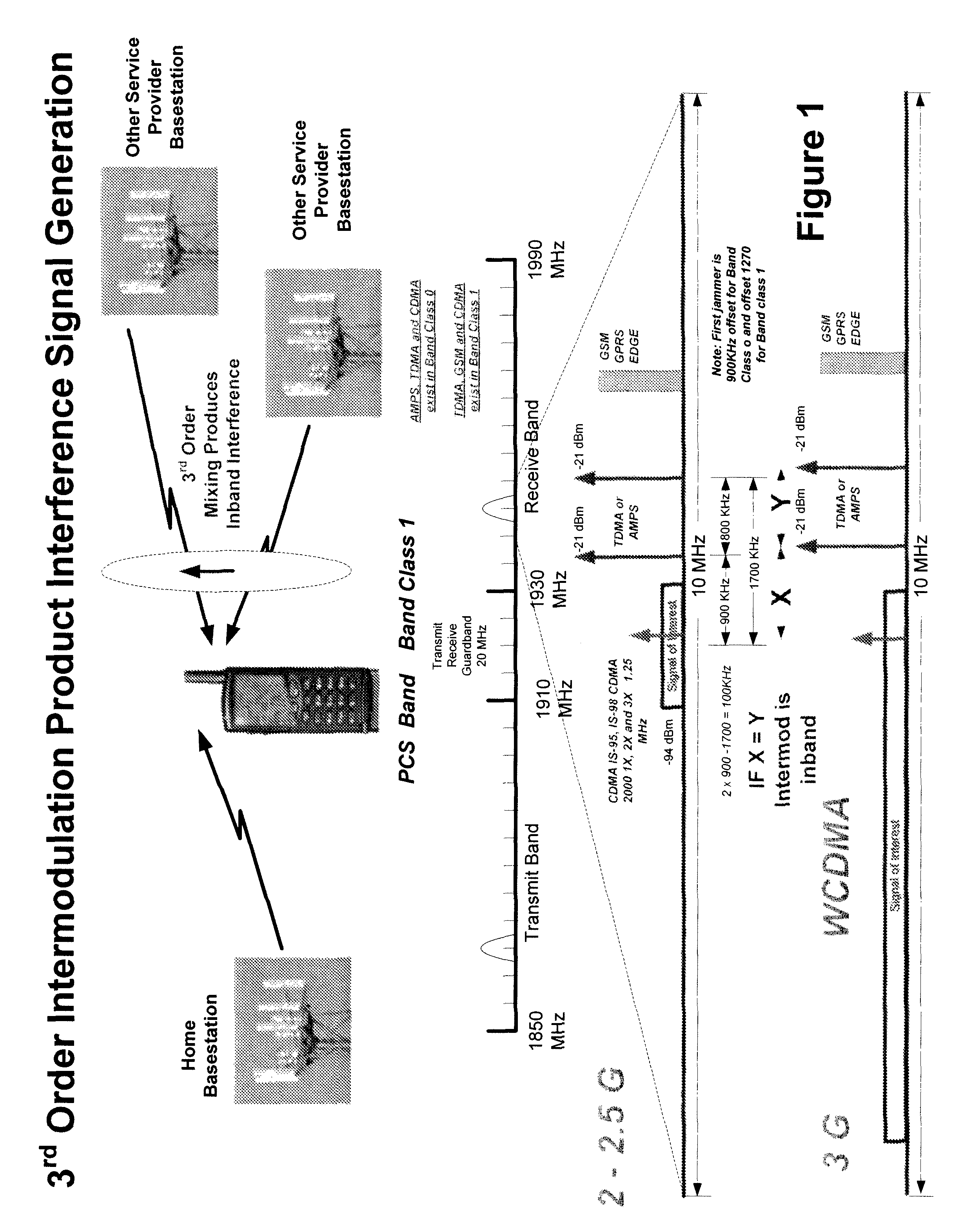
[0042]The detailed description that follows used the PCS band in North America and focuses on CDMA2000 to provide a concrete example for the description of the invention. This is not intended to limit the application of this invention. As one versed in the arts will recognize, this invention is applicable to a wide range of wired and wireless applications and is modulation independent and can be applied to all international bands and radio standards.

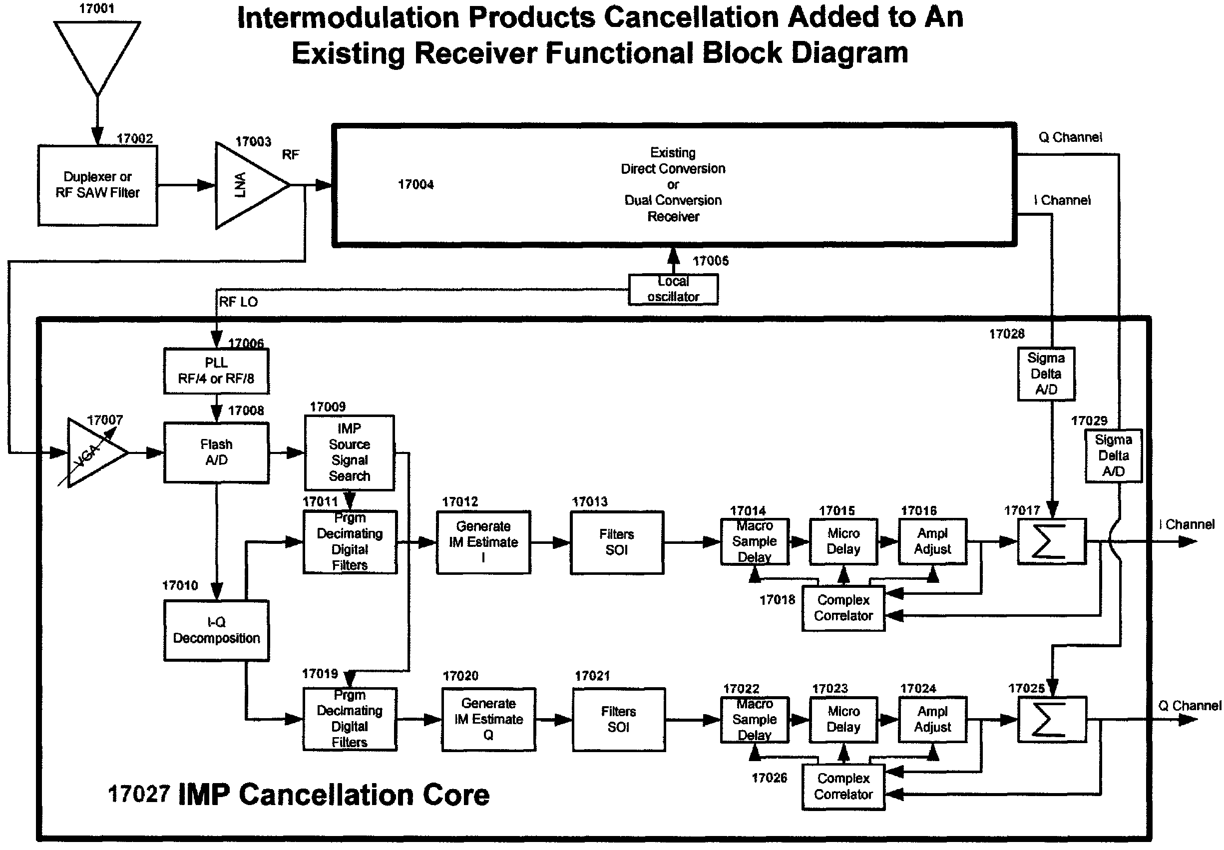
[0043]In one embodiment of this invention, the receive signal is spit after the LNA and one path is processed in a conventional manner to recover the SOI. The other path is used to find the IMP source signals, to generate an IMP cancellation signal and then to cancel the 2nd and 3rd order IMP products that fall in band of the signal of interest in real or near real time.

Search Algorithm

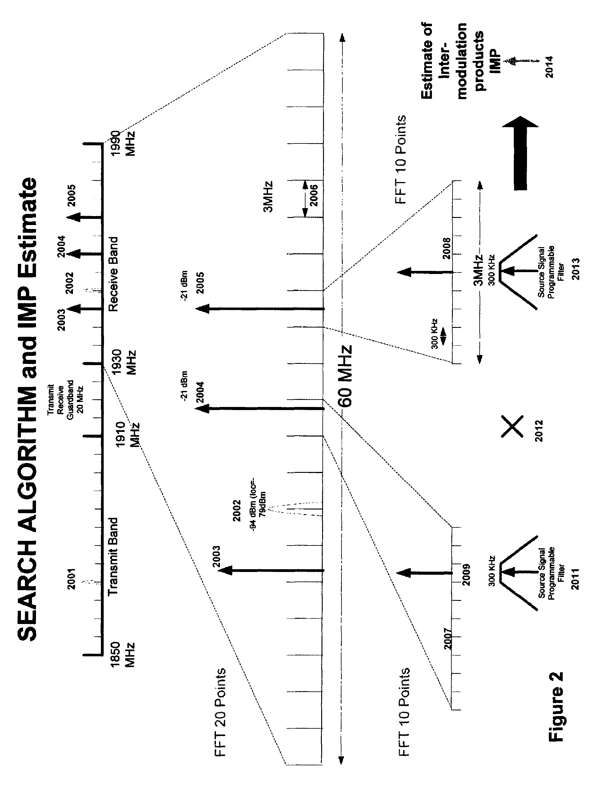
[0044]In one embodiment of this invention, as shown in FIG. 2, the entire receive band of the wireless standard is received by the RF front end of the rec...


PUM


Abstract

A Multi-mode-multi-band direct conversion receiver with complex I and Q channel interference mitigation processing for cancellation of intermodulation products (IMPs) are described. In one embodiment, a method comprising over sampling of the entire receiver passband to acquire the IMP source signals that can generate IMPs within the signal of interest (SOI), generate a coherent complex I-Q channel estimates of the interference, generating estimates of 2nd and 3rd order IMP products, sampling of the transmitter feed thru signal and blocking signals and computing the cross modulation products estimate, using the cross modulation cancellation to cancel of the effects of the on chip transmitter feed thru to support building a single transceiver chip with full duplex operation, and creation of an estimate of the DC offset in the receiver in a closed loop fashion to cancel the DC offset in the I and Q channels independently and simultaneously, and adjusting the rate of update to match system parameters.

Description

FIELD OF THE INVENTION[0001]The field of this invention relates to the field of wired and wireless receivers and the cancellation of interference produced by intermodulation products. It relates to multi-band and multi-mode receivers and the interference mitigation for single and dual conversion radio receivers.BACKGROUND OF THE INVENTIONDefinitions and Termsa.) Signal of Interest (SOI)—this is the target signal which the receiver is processing. It will be a subset of the entire receive band of the receiver.[0002]b.) IMP Source Signals or Source Signals—these are signals in the receive band that are out of band of the SOI, but that can mix in the non-linearities of the receiver and produce intermodulation products that can fall in band of the SOI. Some times also called blocking signals.c.) IM, IMP, IMD—Intermodulation products which are produced by the IMP source signalsd.) IMP Estimate—this is the estimate of the IMP that is developed by the receiver and then used to cancel the in...

Claims


Application Information

Patent Timeline
Patent Type & Authority Patents(United States)
IPC IPC(8): H04B1/10
CPCH04B1/30
Inventor SMITH, FRANCIS J.
Owner SMITH FRANCIS J
Why Eureka
Try Eureka