Multiband planar built-in radio antenna with inverted-L main and parasitic radiators

a built-in antenna and antenna technology, applied in the direction of antenna earthings, substantially flat resonant elements, resonant antennas, etc., can solve the problems of limiting the height of the pifa antenna, the inability to use cellular communications, and the narrow bandwidth of this design for cellular communication

Inactive Publication Date: 2008-01-15
SONY ERICSSON MOBILE COMM AB
View PDF11 Cites 167 Cited by
  • Summary
  • Abstract
  • Description
  • Claims
  • Application Information

AI Technical Summary

Problems solved by technology

Unfortunately, the bandwidth for this design is too narrow for use in cellular communications.
While such an antenna has enough bandwidth for cellular communications, it requires the addition of a parasitic strip.
However, as mobile phones become smaller and smaller, the height of the PIFA antennas are still a limiting factor for decreasing the terminal size.
This, however, is an undesirable modification as the height increase makes the antenna unattractive for small communication devices.
However, prior art antenna designs will still be a limiting factor when developing radio terminals with adequate bandwidth to cover, for example, all of the DCSS, PCS and UMTS frequency bands, at the same time recognizing the desire to provide compact terminals.
The larger distance the better antenna performance, to a certain degree, and since the mobile phones of today must be as small and thin as possible, this is a dilemma.
A more general problem with built-in antennas is not only small band width, but also significantly worse gain performance than a traditional external antenna i.e. Some kind of stub antenna.

Method used


Image

  • Multiband planar built-in radio antenna with inverted-L main and parasitic radiators
  • Multiband planar built-in radio antenna with inverted-L main and parasitic radiators
  • Multiband planar built-in radio antenna with inverted-L main and parasitic radiators

Examples


Embodiment Construction

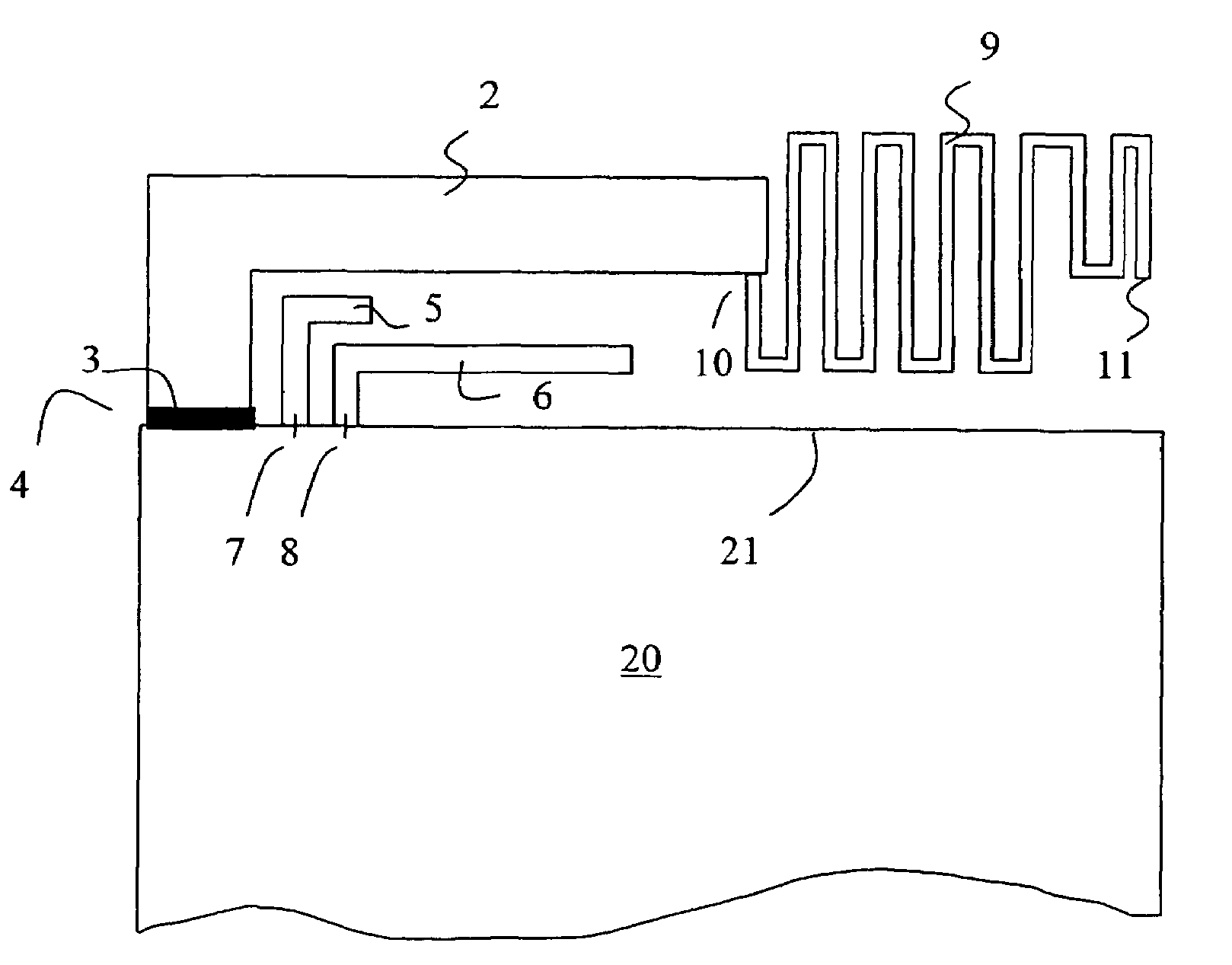
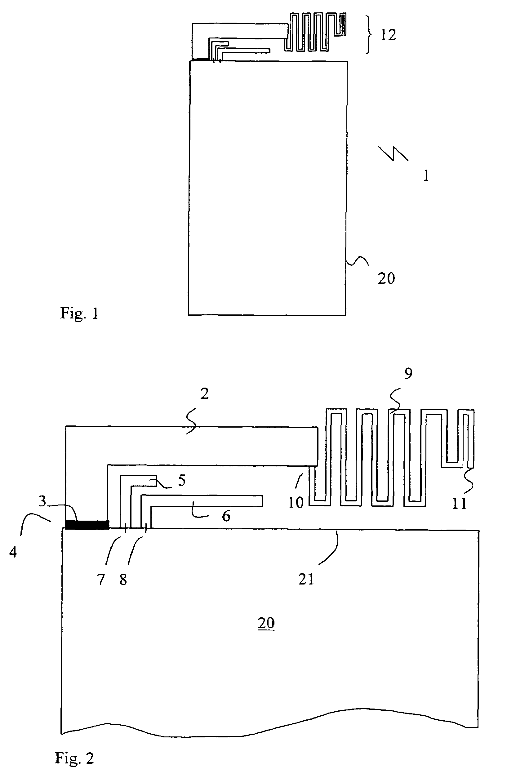
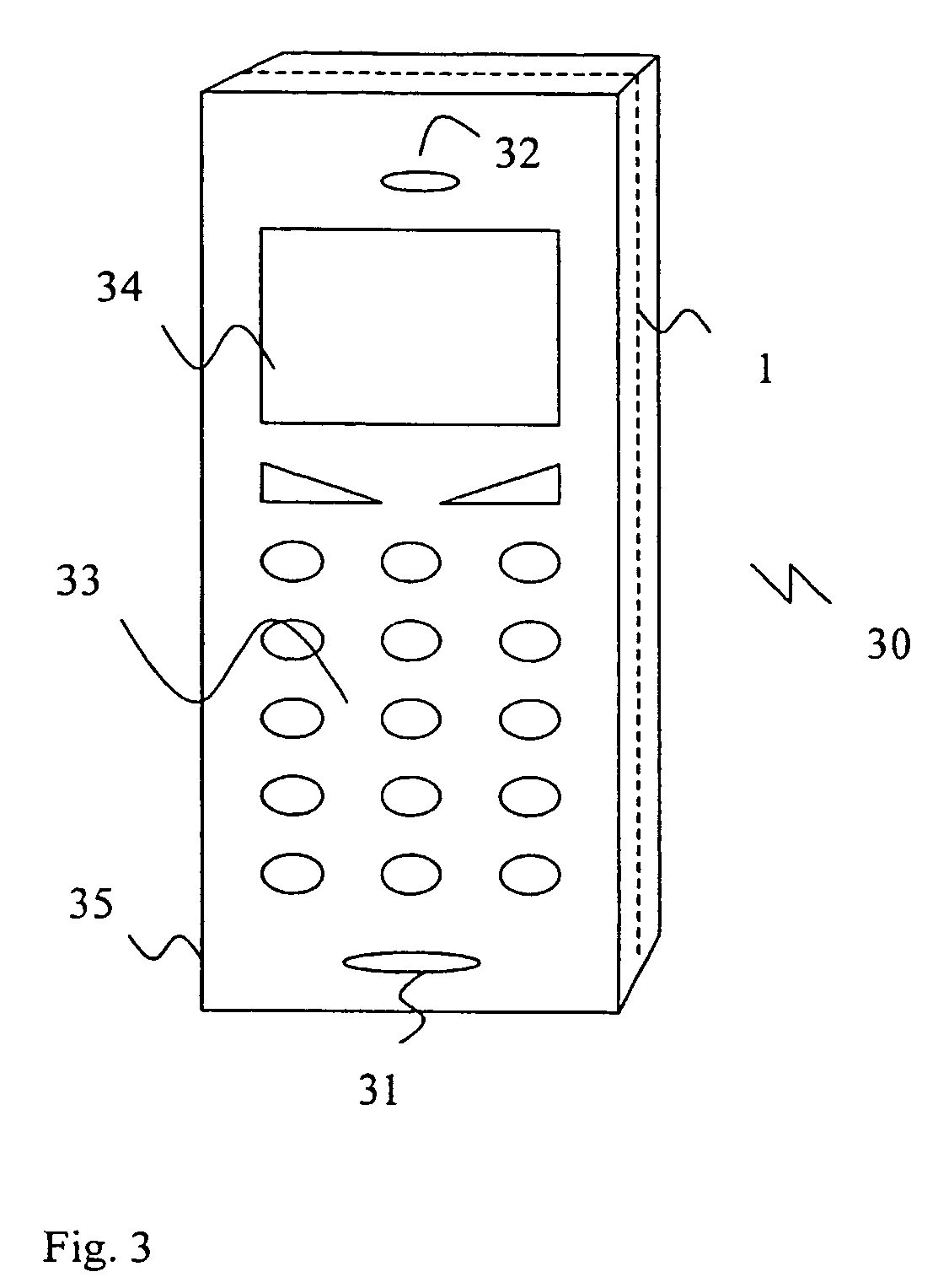
[0034]The present description refers to radio terminals as a device in which to implement a radio antenna design according to the present invention. The term radio terminal includes all mobile equipment devised for radio communication with a radio station, which radio station also may be mobile terminal or e.g. a stationary base station. Consequently, the term radio terminal includes mobile telephones, pagers, communicators, electronic organizers, smartphones, PDA:s (Personal Digital Assistants), vehicle-mounted radio communication devices, or the like, as well as portable laptop computers devised for wireless communication in e.g. a WLAN (Wireless Local Area Network). Furthermore, since the antenna as such is suitable for but not restricted to mobile use, the term radio terminal should also be understood as to include any stationary device arranged for radio communication, such as e.g. desktop computers, printers, fax machines and so on, devised to operate with radio communication ...


PUM


Abstract

A multi-band radio antenna device (1) for a radio communication terminal, comprising a flat ground substrate (20), a flat main radiating element (2, 9) having a radio signal feeding point (3), and a flat parasitic element (5, 6). The main radiating 5 element is located adjacent to and in the same plane as said ground substrate, and preferably dielectrically separated therefrom. The antenna device is suitable for being used as a built-in antenna in portable radio terminals, such as a mobile phone (30).

Description

[0001]This patent application claims the benefit of priority from U.S. Provisional Application Ser. No. 60 / 366,514 filed on Mar. 19, 2002. This application incorporates by reference the entire disclosure of U.S. Provisional Patent Application Ser. No. 60 / 366,514.FIELD OF THE INVENTION[0002]The present invention relates generally to antennas for radio communication terminals and, in particular, to compact built-in antennas devised to be incorporated into portable terminals and having a wide bandwidth to facilitate operation of the portable terminals within different frequency bands.BACKGROUND[0003]Since the end of the 2000th century the cellular telephone industry has had enormous development in the world. From the initial analog systems, such as those defined by the standards AMPS (Advanced Mobile Phone System) and NMT (Nordic Mobile Telephone), the development has during recent years been almost exclusively focused on standards for digital solutions for cellular radio network syste...

Claims


Application Information

Patent Timeline
Patent Type & Authority Patents(United States)
IPC IPC(8): H01Q1/24H01Q1/38H01Q5/00H01Q5/10H01Q5/357H01Q5/385H01Q9/04H01Q9/42H01Q19/00
CPCH01Q1/243H01Q1/38H01Q9/0407H01Q5/385H01Q19/005H01Q5/357H01Q9/42
Inventor ANDERSSON, JOHAN
Owner SONY ERICSSON MOBILE COMM AB
Why Eureka
Try Eureka