Shared functional block multi-mode multi-band communication transceivers

a multi-mode multi-band communication and functional block technology, applied in the field of communication systems, can solve the problems of complex circuitry of personal communication devices such as cellular telephones, a number of power-inefficient components, complex circuitry, etc., and achieve the effect of reducing complexity, power consumption, cost, and siz

Inactive Publication Date: 2006-08-15
CISCO TECH INC
View PDF34 Cites 181 Cited by
  • Summary
  • Abstract
  • Description
  • Claims
  • Application Information

AI Technical Summary

Benefits of technology

[0010]Therefore, it is an object of embodiments of the shared functional block multi-mode multi-band transceiver to provide a system and process for

Problems solved by technology

However, personal communication devices such as cellular telephones often require complex circuitry with a number of power-inefficient components for performing particular functions.
However, GSM is not the only mode of cellular communication.
However, multi-mode, multi-band cellular telephones such as combined CDMA/GSM telephones present a number of design challenges.
The design challenge of producing cellular telephones of minimal siz

Method used


Image

  • Shared functional block multi-mode multi-band communication transceivers
  • Shared functional block multi-mode multi-band communication transceivers
  • Shared functional block multi-mode multi-band communication transceivers

Examples


first embodiment

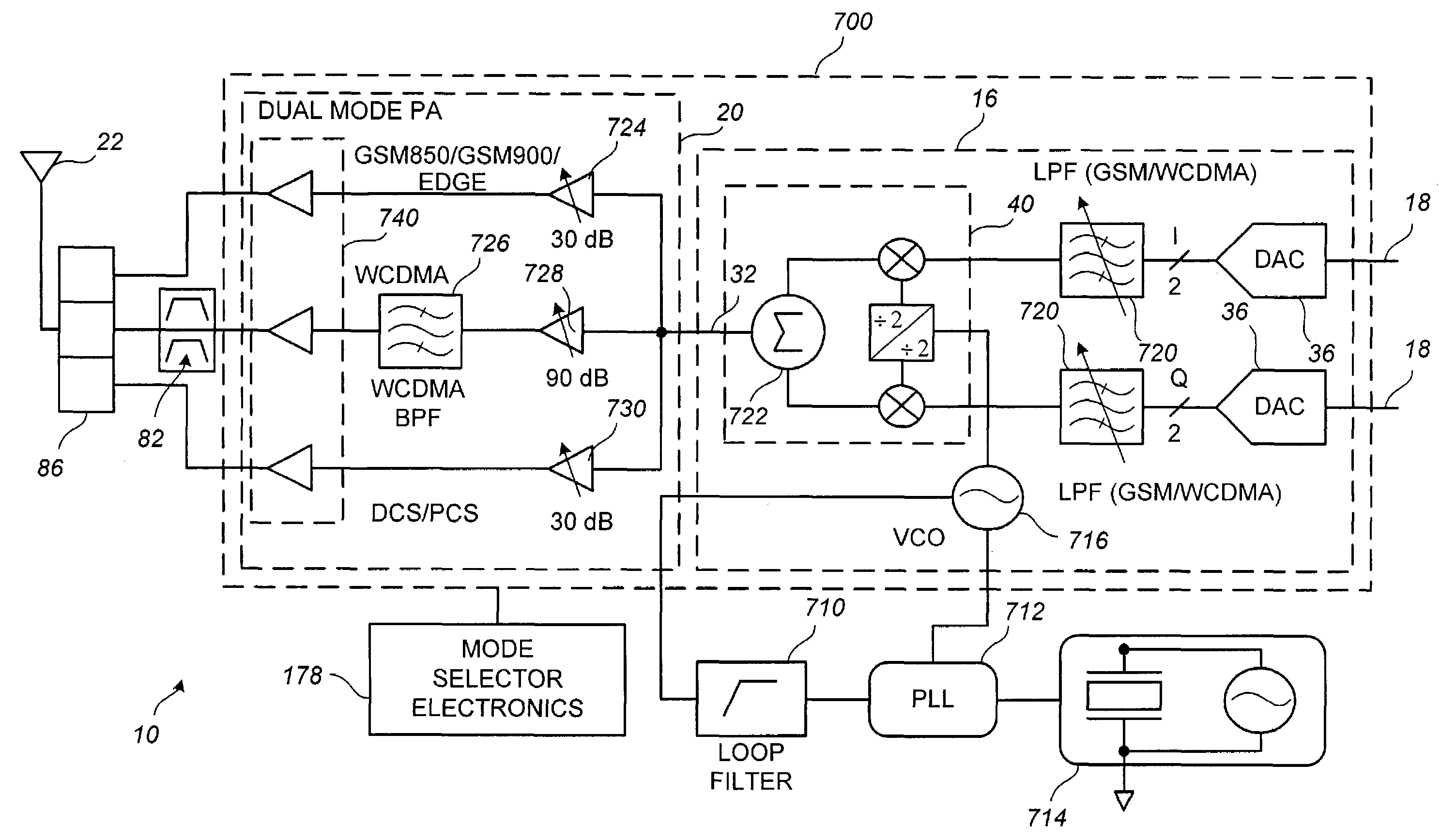
[0093]FIG. 7 illustrates a multi-mode transceiver 10 that uses a direct launch RF signal transmission technique to produce EDGE / GSM, WCDMA, and DCS / PCS compatible signal transmissions. As stated above, EDGE is a modification of GSM that uses similar signal transmission methodologies. Transceiver 10 includes antenna 22, switchplexer 86, duplexer 82, integrated transmitter 700 generally including elements depicted to be “on-chip” i.e., within an integrated circuit, and off-chip elements. Antenna 22 receives and is provided RF signals for transmission via switchplexer 86. Switchplexer 86 controllably routes both transmit to and receive signals from antenna 22 in response to a control signal supplied via mode selector electronics 178. When WCDMA signal transmissions are desired, duplexer 82 couples the integrated transmitter 700 to the switchplexer 86. Duplexer 82 is used to isolate the high and low frequency bands used by WCDMA communication signals.

[0094]Integrated transmitter 700 inc...

second embodiment

[0119]FIG. 11 illustrates a second embodiment for a multi-mode transceiver 10 that receives RF signal transmissions and generates baseband signals for EDGE (GSM), WCDMA, and DCS / PCS compatible communications. The multi-mode transceiver architecture illustrated in FIG. 11 supports a directed (e.g., multiplexed) mode for non-simultaneous operation of WCDMA / GSM or CDMA 2000 / GSM. Transceiver 10 includes antenna 22, switchplexer 86, duplexer 82, integrated receiver 1100, and off-chip elements. Antenna 22 receives RF signals for via switchplexer 86. When WCDMA signal transmissions are desired, duplexer 82 couples the integrated receiver 1100 to the switchplexer 86.

[0120]A remote signal source (not shown) is intercepted by antenna 22 and coupled to integrated receiver 1100 via switchplexer 86 and LNAs 810, 812, and 814. When the transceiver 10 is operating in a WCDMA mode, intercepted signal transmissions are coupled to integrated receiver 1100 via duplexer 82. The intercepted signal trans...


PUM


Abstract

A multiple-mode multiple band transceiver is disclosed. Some embodiments include a multiple-channel transmitter including a plurality of selectable transmit-channel components, the plurality of selectable transmit-channel components sharing at least one element coupled to a modulator, the plurality of selectable transmit channel components forming at least first and second transmit channels configured to generate radio-frequency signals using at least a first and a second multiple-access modulation technique, and a first switch configured to enable at least one of the first and second transmit channels to transmit a communication signal using at least one of the first and the second multiple-access modulation techniques.

Description

CROSS-REFERENCE TO RELATED APPLICATION[0001]This application is a continuation-in-part of U.S. utility application entitled, “System and Process for Shared Functional Block CDMA and GSM Communication Transceivers,” having Ser. No. 09 / 298,315, filed Apr. 23, 1999, now U.S. Pat. No. 6,584,090, which is entirely incorporated herein by reference.BACKGROUND OF THE INVENTION[0002]1. Field of the Invention[0003]The shared functional block multi-mode multi-band transceiver relates generally to communication systems which use radio-frequency (RF) transmitters and receivers (transceivers), and in particular embodiments, to systems and methods for multi-mode, multi-band Code Division Multiple Access (CDMA) and Global System for Mobile (GSM) communication transceivers that share functional blocks to minimize size, weight, complexity, power consumption, cost, etc.[0004]2. Related Art[0005]It has become increasingly important to minimize the size, weight, complexity, power consumption, and cost o...

Claims


Application Information

Patent Timeline
IPC IPC(8): H04B1/40H04M1/00H04B1/707H04B7/26H04W88/06
CPCH04B1/005H04B1/406H04B1/006H04B1/707H04B1/28H04W88/06
Inventor ABDELGANY, MOHYELDEEN FOUADLAUB, DANA VINCENT
Owner CISCO TECH INC
Why Eureka
Try Eureka