Back structure for a chair

Inactive Publication Date: 2010-08-17
WU YAO CHUAN
View PDF5 Cites 27 Cited by
  • Summary
  • Abstract
  • Description
  • Claims
  • Application Information

AI Technical Summary

Benefits of technology

[0007]The primary object of the present invention is to provide a rack structure for a chair that may maintain a user's correct sitting posture by swinging the frame thereof.
[0011]In operation, the frame may be used to support the user comfortably. However, if the user lays on and against the support cushion in an incorrect posture and since the support cushion pressed by the user is located beneath the second connecting tab and the resilient member is attached between the coupling segment and the connecting projection, the user presses the bottom of the frame to swing rearward and the top end of the frame is urged to pull the resilient members to become bent frontward so as to support and conform the shape of the user's back for recovering correct lying postures. On the contrary, if the user lays and against the upper side of the frame by his upper back, the bottom of the frame may swing frontward by using the resilient members so that the support cushion may move frontward to support the user, obtaining comfort with his changing postures.
[0012]To accommodate different users, each of two sides of the frame is provided with a continuous arcuate groove, and each of two ends of the support cushion is disposed with an arcuate protrusion for being fixed into the continuous arcuate groove by an elongated press member. The support cushion may be adjusted upward and downward relative to the frame, thus maintaining the correct sitting posture.
[0013]Furthermore, the support cushion includes foam materials filled therein for increasing comfort.

Problems solved by technology

However, such a conventional chair can not make the user correct his sitting posture if sitting on the chair in an incorrect manner, causing fatigue.

Method used


Image

  • Back structure for a chair
  • Back structure for a chair
  • Back structure for a chair

Examples


Embodiment Construction

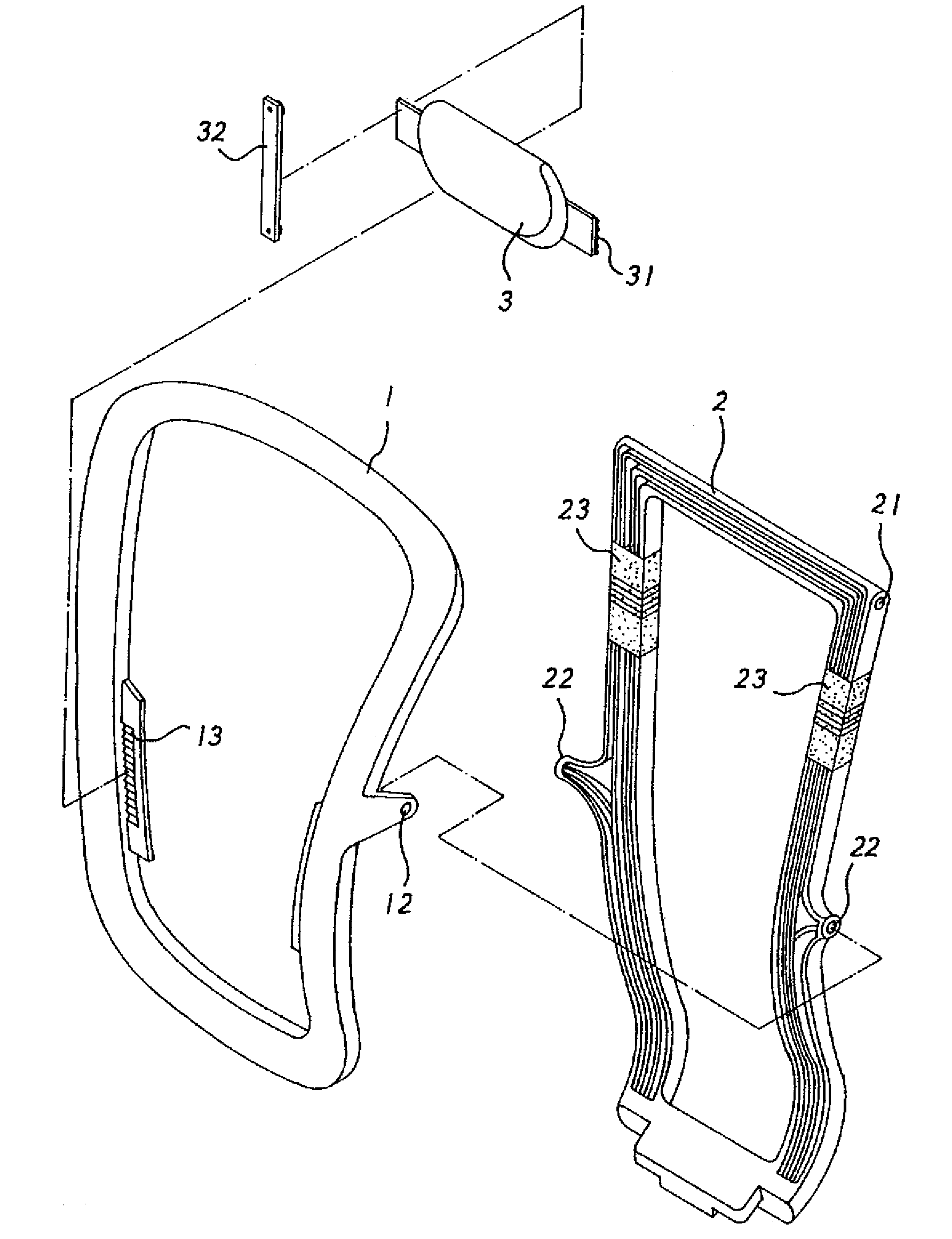
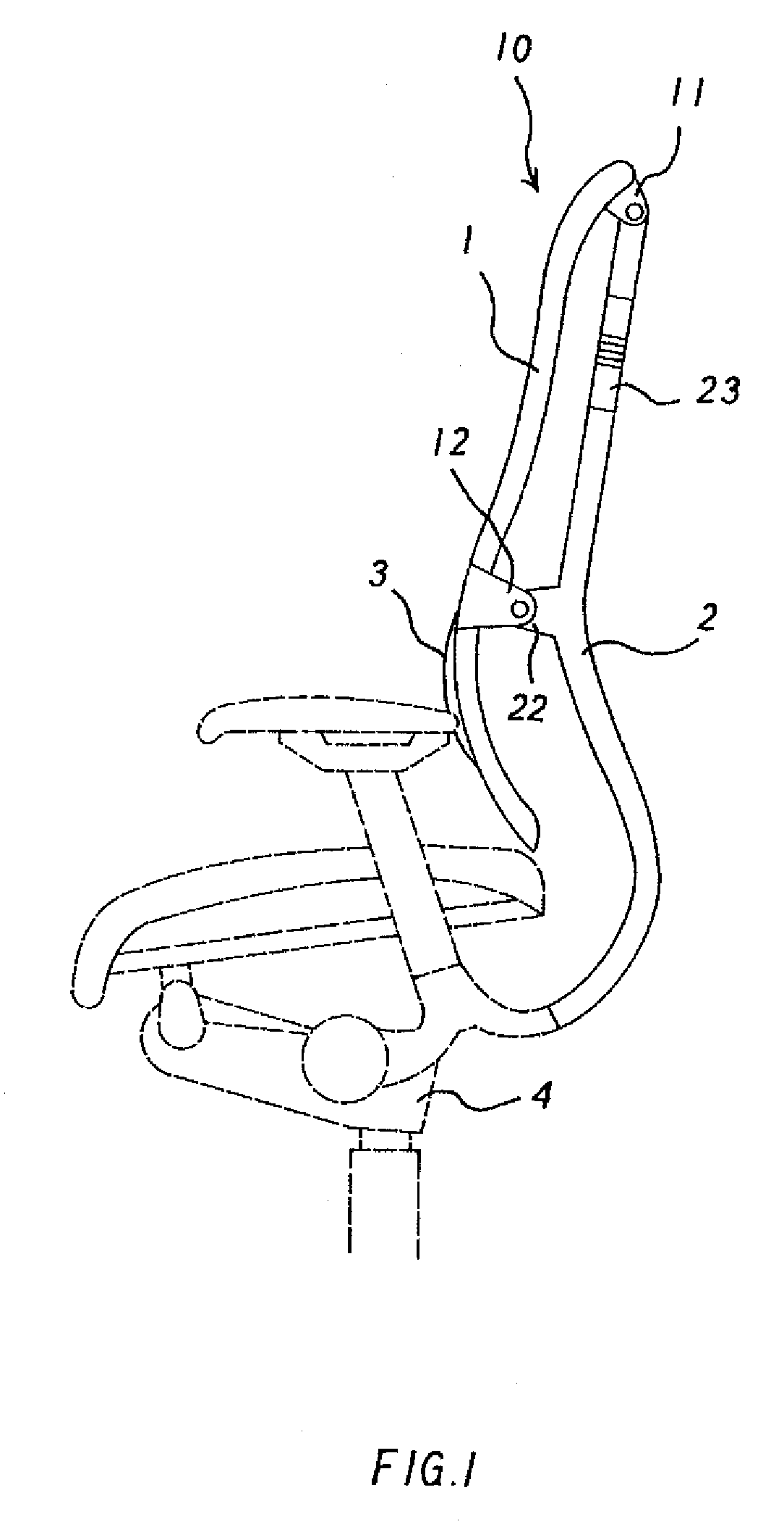
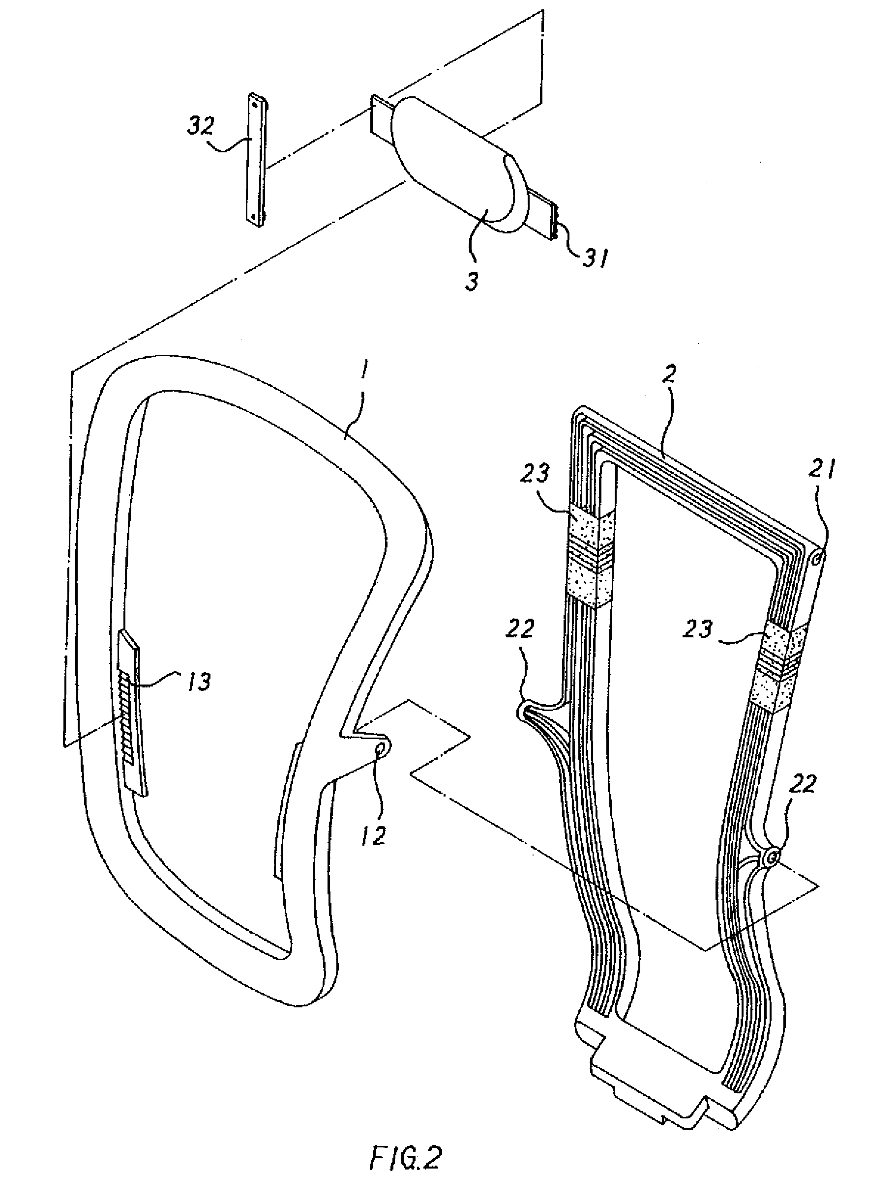
[0021]Referring to FIGS. 3-5, a rack structure for a chair in accordance with the present invention includes a chair back member 10 comprised of a frame 1 and a mounting support 2 (as shown in FIGS. 1 and 2).

[0022]The frame 1 includes a support cushion 3 disposed on the front side thereof for supporting a user's waist correspondingly. The frame 1 further includes two first connecting tabs 11 fixed on the back sides of the top ends of two sides thereof individually and two second connecting tabs 12 formed on and extending from the two sides thereof respectively.

[0023]The mounting support 2 is fixed onto a base 4 and extends upwardly therefrom. The mounting support 2 includes two coupling segments 21 and two connecting projections 22 arranged on the top ends and the intermediate sections of two sides thereof respectively. Between each coupling segment 21 and each connecting projection 22 is couplingly attached a resilient member 23. The first and second connecting tabs 11, 12 of the f...


PUM


Abstract

A rack structure for a chair includes a chair back member having a frame and a mounting support. The frame includes a support cushion disposed on the front side thereof for supporting a user's waist correspondingly. The frame further includes two first connecting tabs fixed on the back sides of the top ends of two sides thereof individually and two second connecting tabs formed on and extending from the two sides thereof respectively. The mounting support is fixed onto a base and extends upwardly therefrom. The mounting support includes two coupling segments and two connecting projections arranged on the top ends and the intermediate sections of two sides thereof respectively. Between each coupling segment and each connecting projection is couplingly attached a resilient member. The first and second connecting tabs of the frame are connected with the coupling segments and the connecting projections of the mounting support individually.

Description

BACKGROUND OF THE INVENTION[0001]1. Field of the Invention[0002]The present invention relates to a rack structure, and more particularly to a rack structure for a chair that may maintain the user's correct sitting posture by swing the frame thereof.[0003]2. Description of the Prior Arts[0004]For comfort, most chairs are equipped with a back rack. Therefore the rack structure will be a requirement for a comfortable chair.[0005]A conventional rack structure includes a frame comprised of a back plate (the back plate includes soft materials, such as foam material, filled therein) for providing comfort as a user sits on the chair and lays against its back. However, such a conventional chair can not make the user correct his sitting posture if sitting on the chair in an incorrect manner, causing fatigue.[0006]The present invention has arisen to mitigate and / or obviate the afore-described disadvantages.SUMMARY OF THE INVENTION[0007]The primary object of the present invention is to provide ...

Claims


Application Information

Patent Timeline
Patent Type & Authority Patents(United States)
IPC IPC(8): A47C7/02
CPCA47C7/462A47C7/448
Inventor WU, YAO-CHUAN
Owner WU YAO CHUAN
Why Eureka
Try Eureka