Method and system for determining particle transmittance of a filter in particle detection system

a particle detection and filter technology, applied in chemical methods analysis, instruments, photoelectric discharge tubes, etc., can solve the problems of significant property damage, dust may seriously affect the output of the detector, and the subsequent removal of the suppressant may be quite hazardous

Active Publication Date: 2010-08-17
GARRETT THERMAL SYST LTD
View PDF8 Cites 9 Cited by
  • Summary
  • Abstract
  • Description
  • Claims
  • Application Information

AI Technical Summary

Problems solved by technology

While the fire itself will cause damage, considerable property damage and also environmental damage may also be caused by operation of the fire suppression system and subsequent removal of the suppressant may be quite hazardous.
A difficulty arises in operation of aspirated smoke detector systems of the above kind in that most atmospheres where smoke or fire detection is required contain dust which may interfere with operation of the system.
For example with optical scatter type detectors, the presence of dust may seriously affect the detector output since dust particles may be generally larger than the particles which are indicative of the presence of smoke or fire and produce more scattered light than those particles.
This causes the effective sensitivity of the detector system to drop.
Unfortunately no known filter has this characteristic transmittance.
One problem is that there is some overlap in sizes between smoke and dust particles, and therefore the functionality of the filter is usually a compromise between arresting all dust and unintentionally arresting some larger smoke particles thereby decreasing the apparent smoke level seen by the detector, and allowing all smoke through with some dust, thereby increasing the apparent smoke level seen by the detector.
Another problem with filters is that they may block over time.
If a filter blocks, it may not transmit smoke particles to the detection chamber, thus reducing the effectiveness of the smoke detector.

Method used


Image

  • Method and system for determining particle transmittance of a filter in particle detection system
  • Method and system for determining particle transmittance of a filter in particle detection system
  • Method and system for determining particle transmittance of a filter in particle detection system

Examples


Embodiment Construction

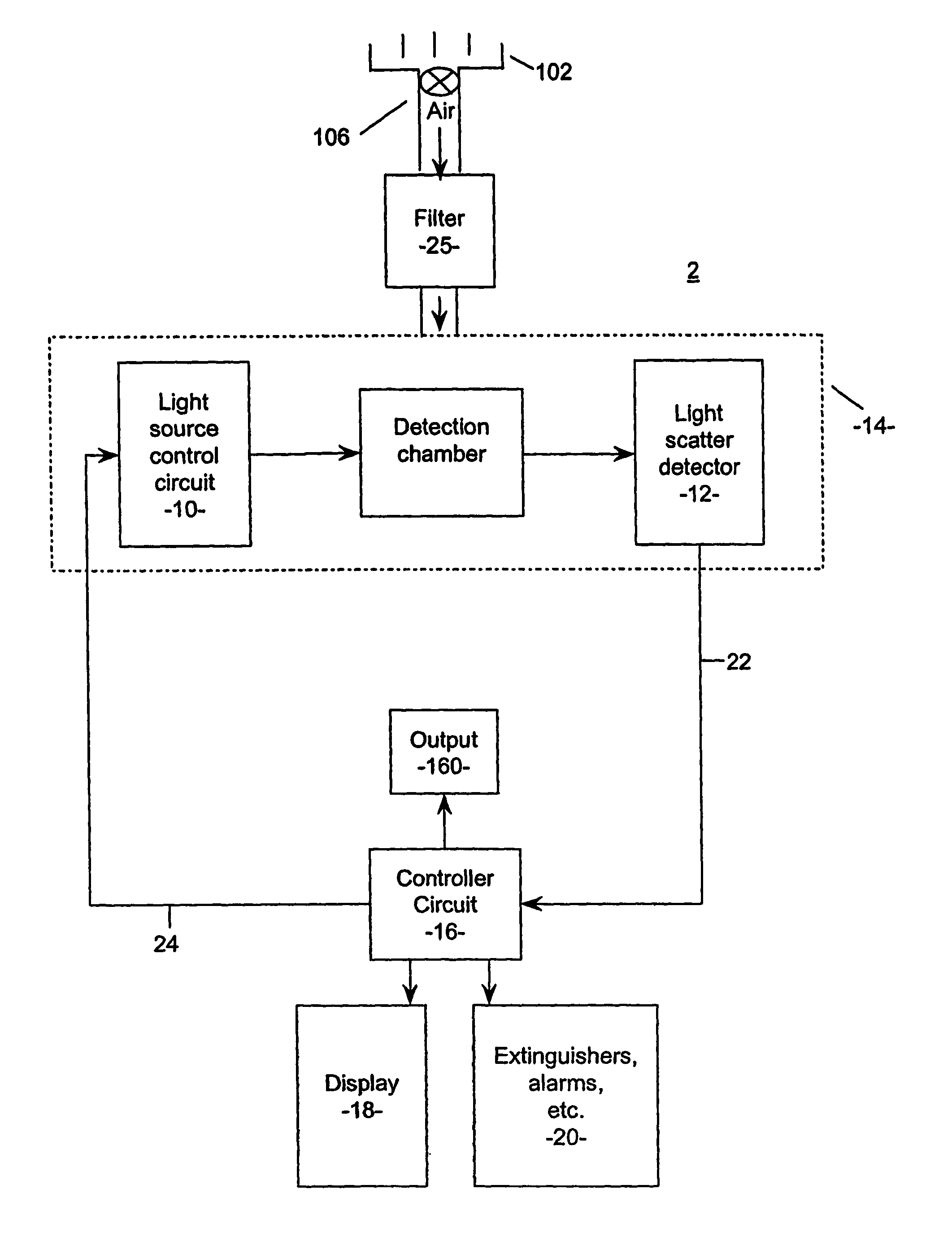
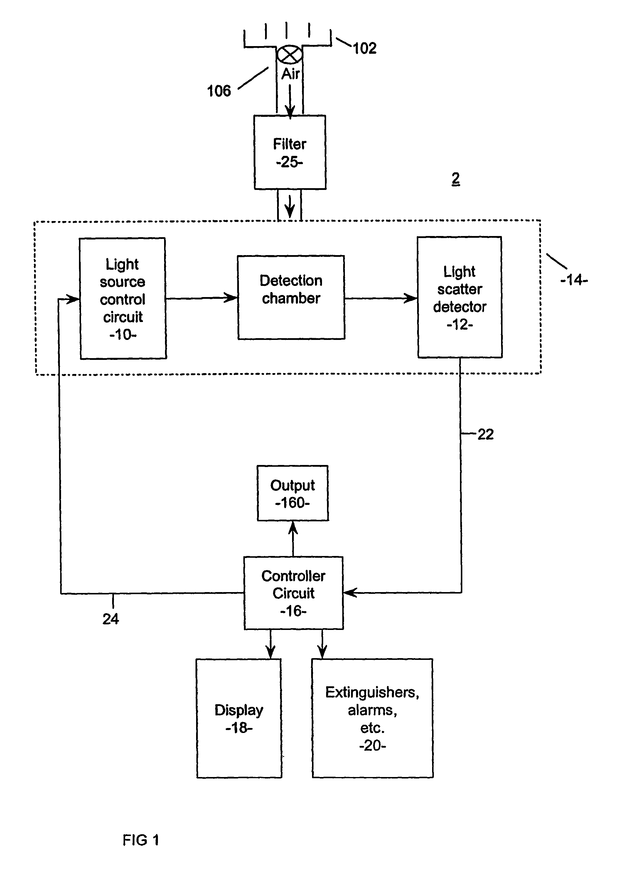
[0117]Initially referring to FIG. 1, an example particle detector system being an aspirated smoke detector 2 is shown having a pipe network 102, a detection chamber 14, a light source 10, a detector 12, an aspirator 106 and a controller 16. Also shown is an output 160, display 18 and alarm and extinguishing equipment 20. A filter 25 is located before the detection chamber 14 to filter unwanted particles from the. From the chamber 14 the sampled air is expelled to the outside environment of the detection system.

[0118]Filter 25, such as a volume foam filter having pores, will accumulate particles within the pores over its life. The particles appear to block the pores, reducing particle transmittance, however the exact mechanisms of filter blocking are not known. Blocked pores will not let dust or all smoke particles through, but may still let air through at flow rates and with pressure drops that are very close to the initial conditions, thus making it impractical to detect a filter w...


PUM


Abstract

The present invention relates to a system for determining particle transmittance Tx of a filter for use with a particle detection system to provide a filter warning for aspirated particle detection systems by detecting a level of first particles having a size indicative of smoke particles and which pass through the detection system; determining an integrated smoke hours value by integrating the detected level of first particles over time; estimating the smoke particle transmittance Tx of the filter by applying a predetermined weighting operation to the integrated smoke hours value. An empirical measure of a filter's particle transmittance Tx, due to at least first particles having a size indicative of smoke particles may be achieved by way of integrating a level of such first particles passing through a particle detection system over time to determine the proportion of smoke particles arrested by a filter, “integrated smoke hours”. The “integrated smoke hours” value is, generally, a measure of cumulative filter blockage over time by smoke like particles and is a measure of a given amount of ambient smoke detected and recorded by a smoke detector system and integrated over the time of exposure of the smoke detector system to the ambient smoke. Using this method it is not necessary to infer the actual “filter load” per-se or, the actual particle mass trapped in the filter.

Description

RELATED APPLICATIONS[0001]This application claims priority to Australian Provisional Patent Application No. 2003903703, filed 18 Jul. 2003 and entitled “Method and System for a Filter” and, the specification thereof is incorporated herein by reference in its entirety and for all purposes.FIELD OF INVENTION[0002]The present invention relates to a filter system for particle detectors. In particular, the present invention relates to a method and system for determining particle transmittance of a filter, for example, for use with a smoke detection system of the kind in which a detector produces an electrical output indicating the concentration, in the air, of particles produced by smoke or fire. In one form, the invention relates to a device and a method of providing a filter warning for aspirated smoke detection systems, and it will be convenient to hereinafter describe the invention in relation to that application. It should be appreciated, however, that the present invention is not l...

Claims


Application Information

Patent Timeline
Patent Type & Authority Patents(United States)
IPC IPC(8): G08B21/00G08B17/10
CPCG08B17/10G08B29/145
Inventor KNOX, RONBOETTGER, KARL
Owner GARRETT THERMAL SYST LTD
Why Eureka
Try Eureka