Shock absorbing device for shoe sole

a technology of shock absorption device and shoe sole, which is applied in the direction of shoes, top-pieces, footwear, etc., can solve the problems of insufficient repulsion function of viscoelastic material, inability to support the foot stably, and energy dissipation as heat, so as to achieve high cushioning function and repulsion function

Active Publication Date: 2010-08-24
ASICS CORP
View PDF85 Cites 78 Cited by
  • Summary
  • Abstract
  • Description
  • Claims
  • Application Information

AI Technical Summary

Benefits of technology

[0028]Therefore, an object of the present invention is to provide a shock absorbing device for a shoe sole performing a high cushioning function and repulsion function by absorbing and storing the impact load of landing sufficiently.

Problems solved by technology

However, when viscoelastic material having a small Young's modulus such as foamed resin used for a cushioning member of the shoe sole is deformed, energy is dissipated as heat and so on.
Accordingly, generally, such viscoelastic material cannot perform the repulsion function sufficiently.
However, since such repulsive members have substantially the same size as the foot and supports the whole of the foot with a curved surface, it cannot support the foot stably.
However, the energy stored in the member due to stretching is much smaller than the energy stored in the member due to bending.
Therefore, this shoe sole also cannot store energy sufficiently.
However, in the period during which the initial landing is shifted to the foot-flat stance, energy cannot be stored sufficiently and therefore cannot be returned sufficiently.

Method used


Image

  • Shock absorbing device for shoe sole
  • Shock absorbing device for shoe sole
  • Shock absorbing device for shoe sole

Examples


first embodiment

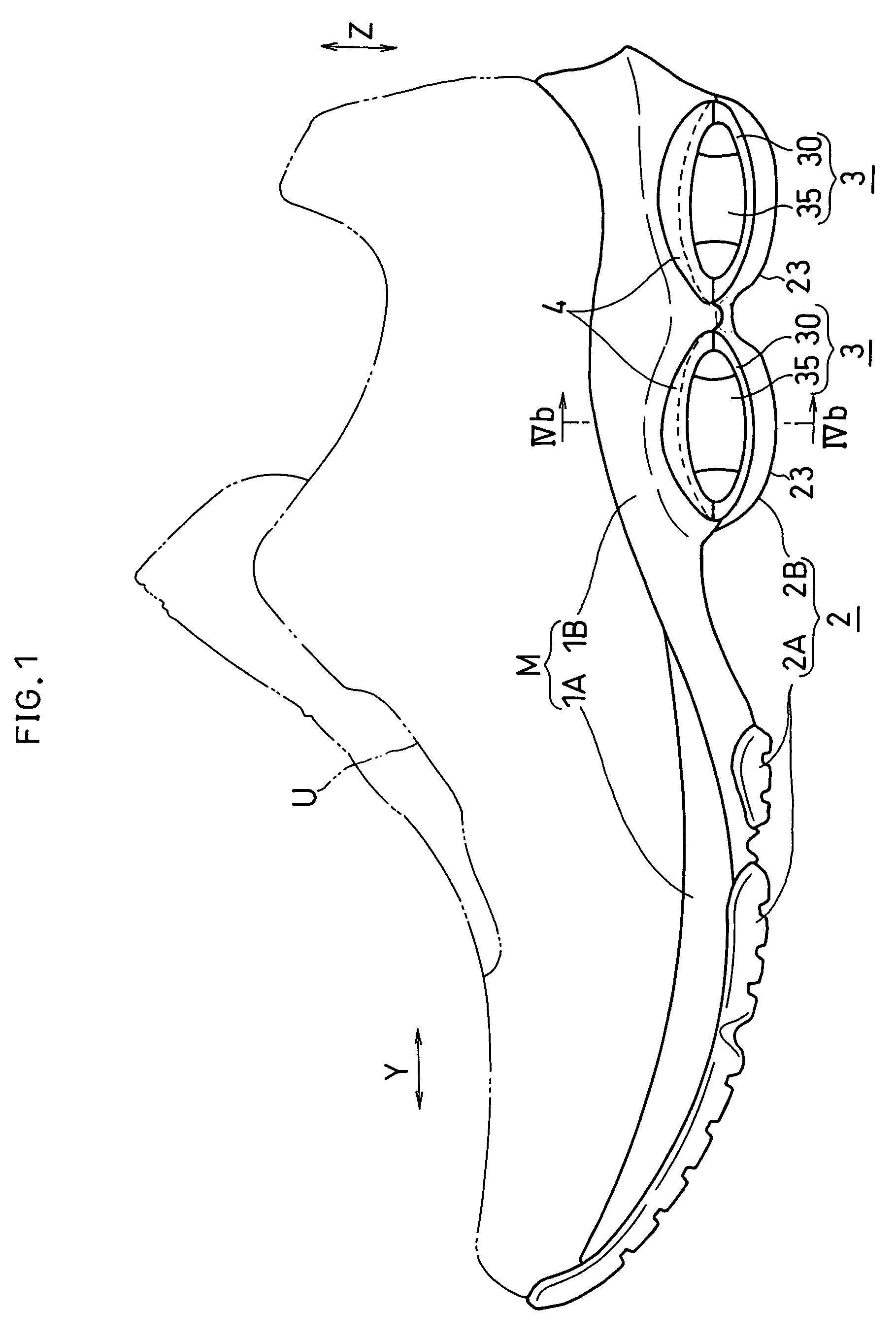
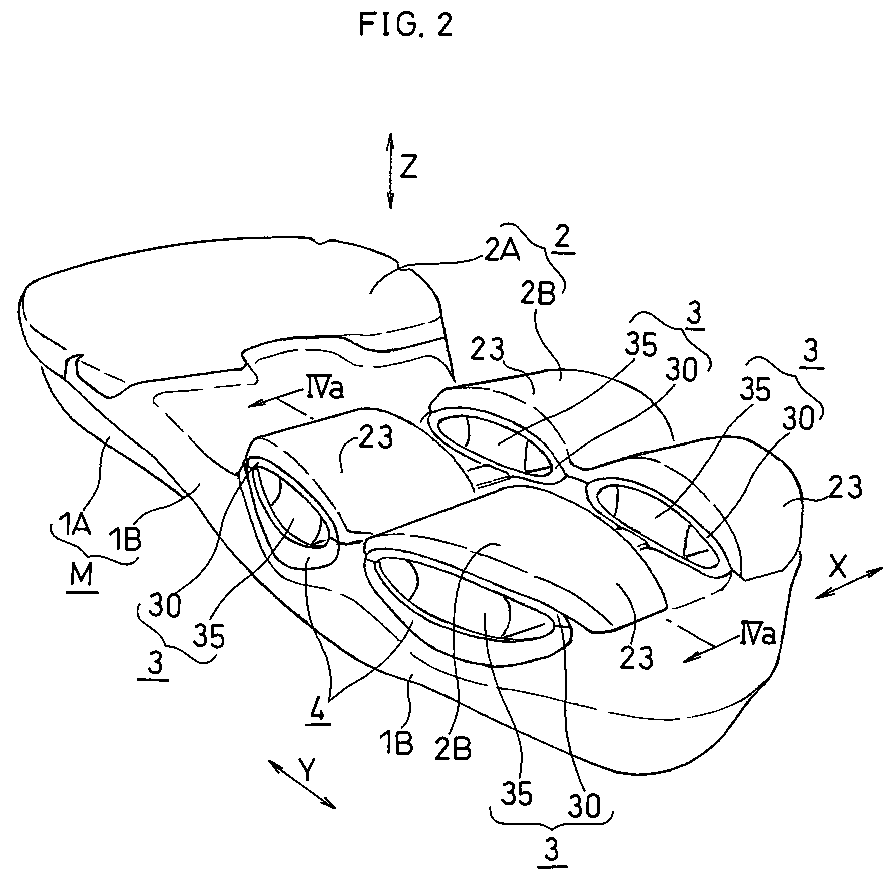
[0102]FIGS. 1 to 4 show a first embodiment of the present invention.

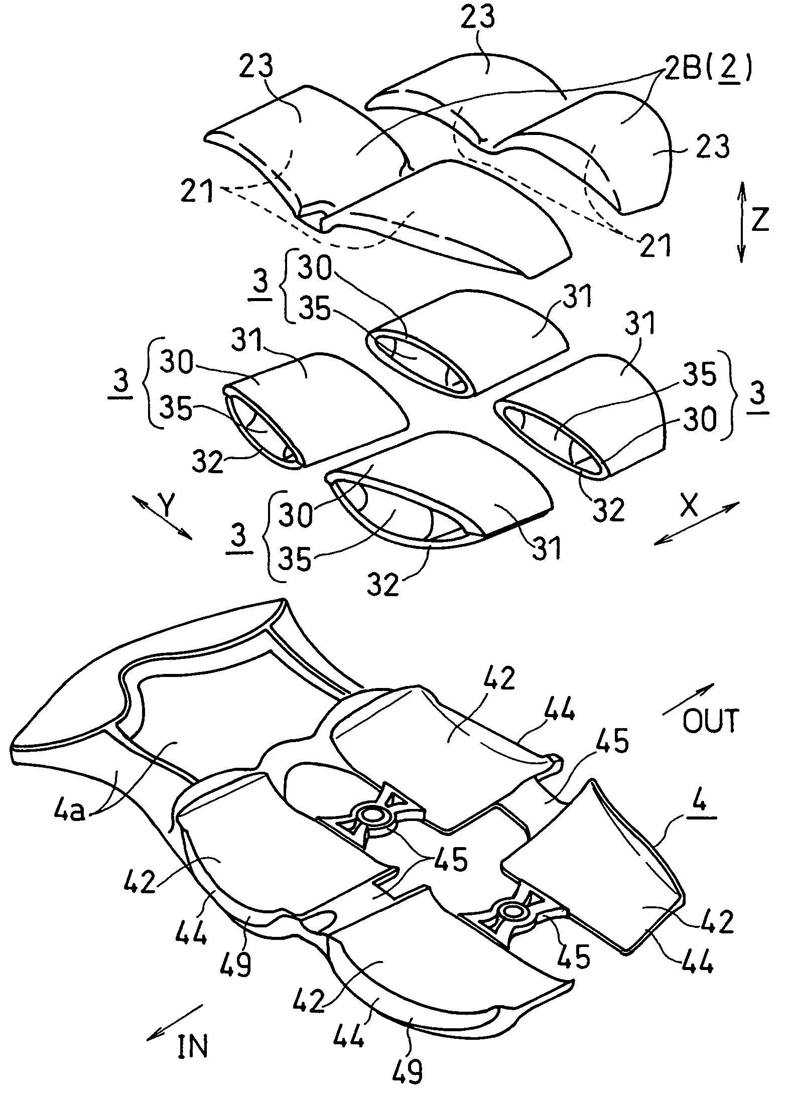
[0103]As shown in FIG. 1, a shoe sole of this embodiment includes a midsole (an example of supporting element) M, an outer sole 2 and deformation elements 3. The midsole M is formed by vertically bonding a first midsole body 1A which is arranged in an upside and a second midsole body 1B which is arranged in a downside. The outer sole 2, a so-called shank (not shown) etc. are disposed on bottom surfaces of the midsole bodies 1A, 1B. An insole (not shown) is bonded onto the first midsole body 1A. Each midsole body 1A, 1B is, for example, formed of a material suitable for shock absorption, i.e. a midsole material such as resin foam of EVA (ethylene-vinyl acetate copolymer), polyurethane or the like. Above the midsole M and the insole, an upper U that is suitable for covering the instep of the foot is disposed. The outer sole 2 that gets contact with the ground surface or the floor surface at the time of landing is form...

second embodiment

[0166]FIG. 5 shows the second embodiment. Note that, in the description of the following embodiments, the parts which are identical or corresponding to those of the first embodiment are designated by the same reference numerals as the first embodiment and the detailed description thereof will be omitted.

[0167]In this embodiment, as shown in FIG. 5, the deformation elements 3 is also provided on the medial and lateral sides of the fore foot part of the foot in addition to the rear foot part of the foot. This deformation element 3 consists of the tubular part 30. That is, unlike the first embodiment, there is no cushioning member within the tubular part 30, and therefore, the tubular part 30 is hollow on the inside.

[0168]In this embodiment, the connecting member for retaining the tubular part 30 is not provided, and the upper portion 32 of the tubular part 30 (lower half of the tubular part 30 in FIG. 5) is directly fit into the second curved surface 12 of the midsole M. The upper por...

third embodiment

[0170]FIGS. 17 to 19 show the third embodiment.

[0171]In this embodiment, as shown in FIG. 17, the connecting member 4 is provided so as to extend from the rear foot part to the arch portion of the foot. A portion of the connecting member located on the arch portion of the foot constitutes a shank (reinforcing device) 4a for restraining distortion of the arch portion.

[0172]For example, a structure as disclosed in WO2005 / 037002 (PCT / JP2004 / 015042), the content of which is hereby incorporated herein by reference, may be employed for this shank 4a.

[0173]In this embodiment, the Young's modulus of the connecting member 4 is set larger than that of the midsole M and smaller than that of the tubular part 30, while, in the first embodiment, the Young's modulus of the connecting member 4 is about the same as that of the tubular part 30. Since such setting of this embodiment enables the connecting member 4 to retain the tubular parts 30 more softly, the upper portion 32 (FIG. 18) of the tubul...


PUM


Abstract

A shock absorbing device for a shoe sole according to the present invention comprises: an outer sole 2; a midsole M that is disposed above the outer sole 2; and a deformation element 3 disposed between the outer sole 2 and the midsole M. The deformation element 3 is joined to the bottom surface of the midsole M and is joined to the upper surface of the outer sole 2. The deformation element has a tubular part 30 in a flat tubular form, and Young's modulus of a material constituting the tubular part 30 is greater than both that of a material constituting the midsole M and that of a material constituting the outer sole 2. The tubular part has a lower portion that is curved so as to be convex downwards and thereby undergoes bending deformation due to a shock at landing.

Description

TECHNICAL FIELD[0001]The present invention relates to a shock absorbing device of a shoe sole.BACKGROUND ART[0002]The cushioning function of absorbing and alleviating the shock at landing is demanded in shoe soles, in addition to the lightness in weight and the function of supporting the foot stably. Recently, shoe soles having the repulsion function (rebound function) in addition to the above-mentioned functions have been presented. The repulsion function refers to the function of storing the impact energy at landing as deformation energy and emitting the energy of deformation when disengaging from the ground. This function is useful for improving exercise ability of a wearer.[0003]By compressing or bending an element of the shoe sole, the deformation energy is stored in the element. However, when viscoelastic material having a small Young's modulus such as foamed resin used for a cushioning member of the shoe sole is deformed, energy is dissipated as heat and so on. Accordingly, g...

Claims


Application Information

Patent Timeline
Patent Type & Authority Patents(United States)
IPC IPC(8): A43B13/28
CPCA43B13/181A43B13/189A43B13/20A43B13/206A43B21/26
Inventor NISHIWAKI, TSUYOSHIFUJITA, HISANORIKUROSAKI, KIYOMITSU
Owner ASICS CORP
Why Eureka
Try Eureka