Bearing plate group and bearing plate thereof

A technology for carrying trays and carrying surfaces, applied to rigid containers, containers to prevent mechanical damage, containers with multiple items, etc., can solve the problems of object 9 damage, increased packaging costs, occupation, etc., to increase support and strengthen Structural strength and the effect of increasing the contact area

Inactive Publication Date: 2011-05-04
AU OPTRONICS CORP
View PDF0 Cites 5 Cited by
  • Summary
  • Abstract
  • Description
  • Claims
  • Application Information

AI Technical Summary

Problems solved by technology

[0005] However, in the tray group A1, although the retaining wall structure 12 is stacked and engaged as the side direction (such as Figure 1A The buffer structure in direction X and direction Y), but the strength of retaining wall structure 12 is still insufficient
Therefore, when the tray set A1 is placed in a packing box (not shown in the figure), it is often necessary to use items such as foam to be placed between the tray set A1 and the packing box to increase the cushioning function, which also causes packaging costs. The increase also means that part of the space in the

Method used


Image

  • Bearing plate group and bearing plate thereof
  • Bearing plate group and bearing plate thereof
  • Bearing plate group and bearing plate thereof

Examples


Embodiment Construction

[0067] A set of trays and trays thereof according to preferred embodiments of the present invention will be described below with reference to related drawings, wherein the same components will be described with the same symbols.

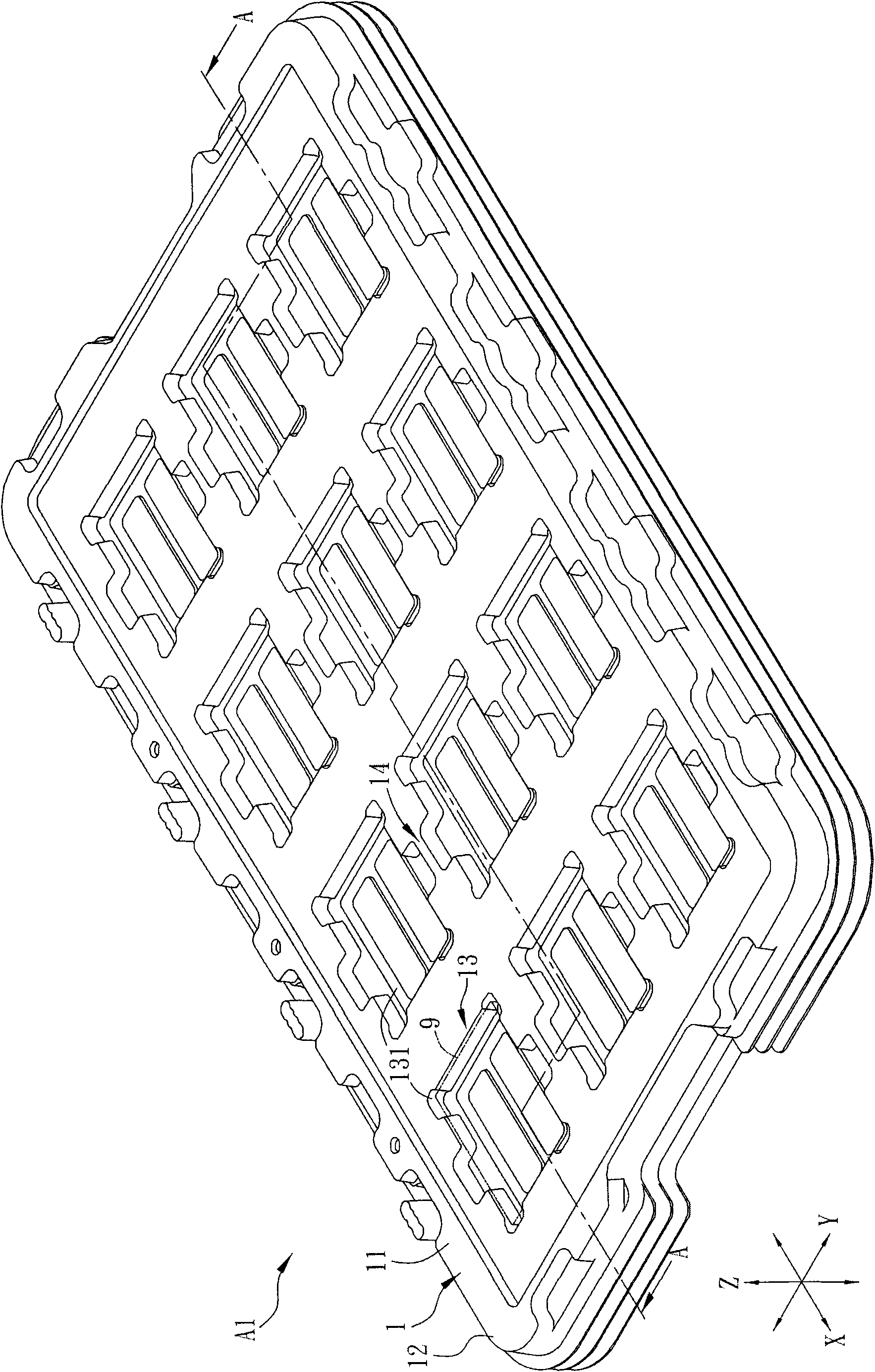
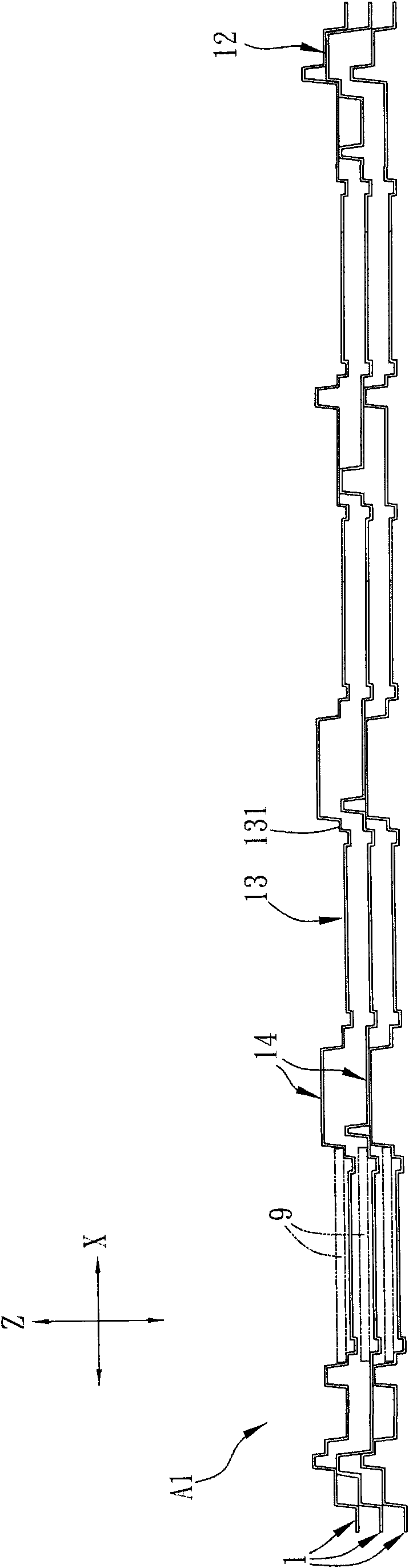
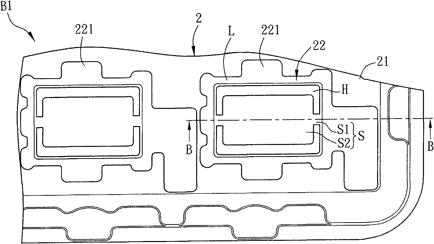
[0068] Please refer to Figure 2A and Figure 2B shown, where Figure 2A It is a partial schematic diagram of the carrier group B1 of the preferred embodiment of the present invention, Figure 2B For the carrier group B1 along Figure 2A Sectional view of the B-B line in the middle. The tray group B1 includes at least two trays 2 stacked horizontally at 180°, and each tray 2 includes a body 21 , a loading structure 22 , a first buffer structure 23 and a second buffer structure 24 .

[0069] The material of the body 21 can be, for example, plastic or polymer, such as polyethylene terephthalate (PET) or polystyrene (PS). The bearing structure 22 is arranged in an array in the body 21 and includes a plurality of bearing grooves 221. Each bearing gr...


PUM


Abstract

The invention discloses a bearing plate group and a bearing plate thereof. The bearing plate contains a body, a bearing structure, a first buffer structure and a second buffer structure, wherein the bearing structure is arranged in the body and contains a plurality of bearing grooves; each bearing groove contains a bearing surface and an elastomer; the bearing surface is around the elastomer; the first buffer structure is on one side of the bearing plate; and the second buffer structure is opposite to the first buffer structure and on the other side of the bearing plate.

Description

[0001] This application is a divisional application based on the prior application 200910145491.8. technical field [0002] The invention relates to a set of carrying disks and the carrying disks thereof. Background technique [0003] In various electronic products (such as mobile phones), a display panel is often required as a human-machine interface. During the transportation of the display panel before assembly, in order to avoid damage to the display panel due to collision, the industry often uses a carrier plate to carry the display panel as a buffer protection. [0004] Please refer to Figure 1A and Figure 1B shown, where Figure 1A is a schematic diagram of the carrier disc group A1 in the prior art, Figure 1B For the carrier group A1 along Figure 1A A cross-sectional view of the line A-A in the middle. The tray group A1 includes at least three trays 1 , the trays 1 are horizontally stacked 180° opposite each other, and each tray 1 has a body 11 , a retaining w...

Claims


Application Information

Patent Timeline
IPC IPC(8): B65D71/70B65D81/02
Inventor 张哲志
Owner AU OPTRONICS CORP
Why Eureka
Try Eureka