Bearing with cage-mounted sensors

a technology of cage-mounted sensors and bearings, which is applied in the direction of instruments, force/torque/work measurement, temperature measurement of moving solids, etc., can solve the problems of not being able to easily inspect the anti-friction bearing, and the other conditions under which the bearing operates are not discernible from visual inspection

Active Publication Date: 2010-08-24
THE TIMKEN CO
View PDF16 Cites 24 Cited by
  • Summary
  • Abstract
  • Description
  • Claims
  • Application Information

AI Technical Summary

Problems solved by technology

Moreover, seals often close the ends of antifriction bearing.
Thus, one does not easily inspect an antifriction bearing to determine conditions within its interior.
Apart from conditions that might reveal themselves with disassembly of a bearing, other conditions under which a bearing operates are not discernible from visual inspections.
For example, one cannot by visual observations determine the load applied to a bearing or the torque transmitted through the shaft or other component on which the bearing is mounted.
Likewise, the temperature at which a bearing operates does not reveal itself to visual observations, but an elevation in temperature certainly signals the onset of problems, and an increase in temperature owing to a lack of lubrication will first manifest itself along the raceways and other critical surfaces.
However, extracting information about such conditions has proven to be difficult.
Not only are the interiors of antifriction bearings generally inaccessible, but also, the rolling elements, which revolve within them, interfere with instrumentation designed to monitor the interiors of such bearings.

Method used


Image

  • Bearing with cage-mounted sensors
  • Bearing with cage-mounted sensors
  • Bearing with cage-mounted sensors

Examples


Embodiment Construction

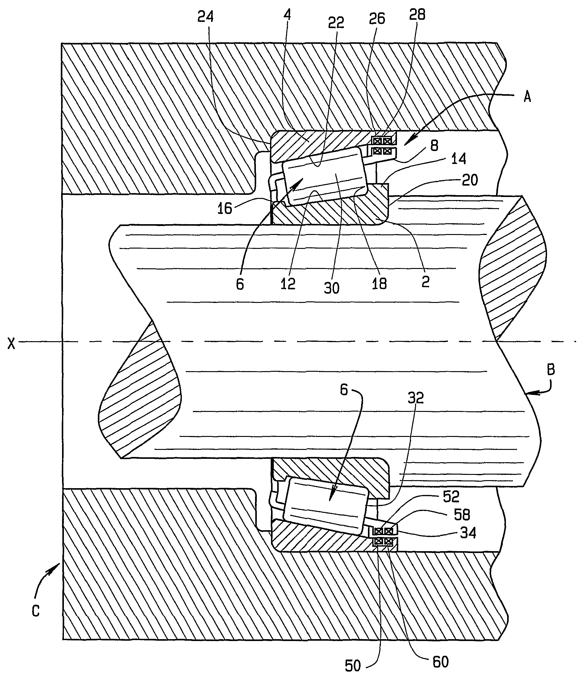
[0023]Referring now to the drawings and in particular to FIG. 1, an antifriction bearing in the form of a tapered roller bearing A supports a shaft B within a housing C and enables the shaft B to rotate within the housing C or the housing C to rotate around the shaft B, in either event about an axis X which is the axis of the bearing A. During the rotation, the bearing A produces signals, which reflect or are indicative of conditions within its interior. The conditions are generally transient, and exist only during the operation of the bearing A.

[0024]Moreover, they are best determined from the interior of the bearing A itself and in some instances can only be derived from the bearing interior. Typical conditions are load, torque, temperature, and angular velocity.

[0025]The bearing A includes an inner race in the form of a cone 2 which fits around the shaft B, an outer race in the form of a cup 4 which fits into the housing C, and rolling elements in the form of tapered rollers 6 ar...


PUM


Abstract

An antifriction bearing (A) for accommodating rotation about an axis (X) comprises an inner race (2) having a raceway (12), an outer race (4) having a raceway (22), rolling elements (6) positioned between the inner and outer races (2, 4) and contacting the raceways (12, 22) of those races (2, 4) so that when relative rotation occurs between the races (2, 4) the rolling elements (6) roll along the raceways (12, 22), a cage (8) positioned between the inner and outer races (2, 4) and having pockets (40) in which the rolling elements (6) are received with the cage (8) being rotatable between the races (2, 4) as the rolling elements (6) roll along the raceways (12, 22), the outer race (4) having a power transmitting coil (50) and a receiver (60), the cage (8) having a power receiving coil (52), a sensing unit (D) for sensing a condition of the bearing (A), and a transmitter (54) for sending a signal indicative of the sensed condition of the bearing (A) to the receiver (60).

Description

CROSS-REFERENCE TO RELATED APPLICATIONS[0001]This application is a United States national phase under 35 USC §371 of PCT / US2006 / 003043, filed Jan. 30, 2006, which claims the benefit of U.S. Provisional Application No. 60 / 649,298, filed on Feb. 1, 2005, and entitled BEARING WITH CAGE-MOUNTED SENSORS. The disclosure of the above application is incorporated herein by reference.TECHNICAL FIELD[0002]This invention relates in general to antifriction bearings and, more particularly, to an antifriction bearing having cage-mounted sensors to monitor one or more conditions within the bearing.BACKGROUND ART[0003]Where shafts or other components of machinery rotate, one usually finds antifriction bearings. These bearings minimize friction by interposing small rolling elements between the rotatable machine component and the stationary component in which or on which the rotatable component revolves. Typically, the rolling elements move along raceways that are on inner and outer races with one fit...

Claims


Application Information

Patent Timeline
Patent Type & Authority Patents(United States)
IPC IPC(8): F16C32/04G01P3/66
CPCG01P3/443G01P3/487F16C19/364F16C19/52F16C33/4635G01L5/0023F16C41/004F16C41/007F16C41/008G01K13/08F16C33/58F16C33/38F16C33/46G01P3/44G01L5/00
Inventor VARONIS, ORESTES J.
Owner THE TIMKEN CO
Why Eureka
Try Eureka