Defined brake pad abutment

a technology of abutments and brake pads, applied in the field of vehicle brakes, can solve problems such as difficulty in pinpointing, and achieve the effect of facilitating the diagnosis of nvh concerns during braking operations and defining and repeating the contact location

Inactive Publication Date: 2010-08-31
KELSEY HAYES CO
View PDF11 Cites 29 Cited by
  • Summary
  • Abstract
  • Description
  • Claims
  • Application Information

AI Technical Summary

Benefits of technology

[0012]The present invention has the advantage of maintaining defined and repeatable contacting location between ear portions of a brake pad and respective abutting clips. Maintaining defined and repeatable contact locations between both abutting surfaces assists in diagnosing NVH concerns during braking operations.

Problems solved by technology

In a braking system having noise, vibration, and harshness (NVH) concerns, one of the factors which causes difficulty in pinpointing the source of the NVH concern is when contact abutment surfaces between a respective ear portion and a respective groove vary from one brake pad to the next.

Method used


Image

  • Defined brake pad abutment
  • Defined brake pad abutment
  • Defined brake pad abutment

Examples


Embodiment Construction

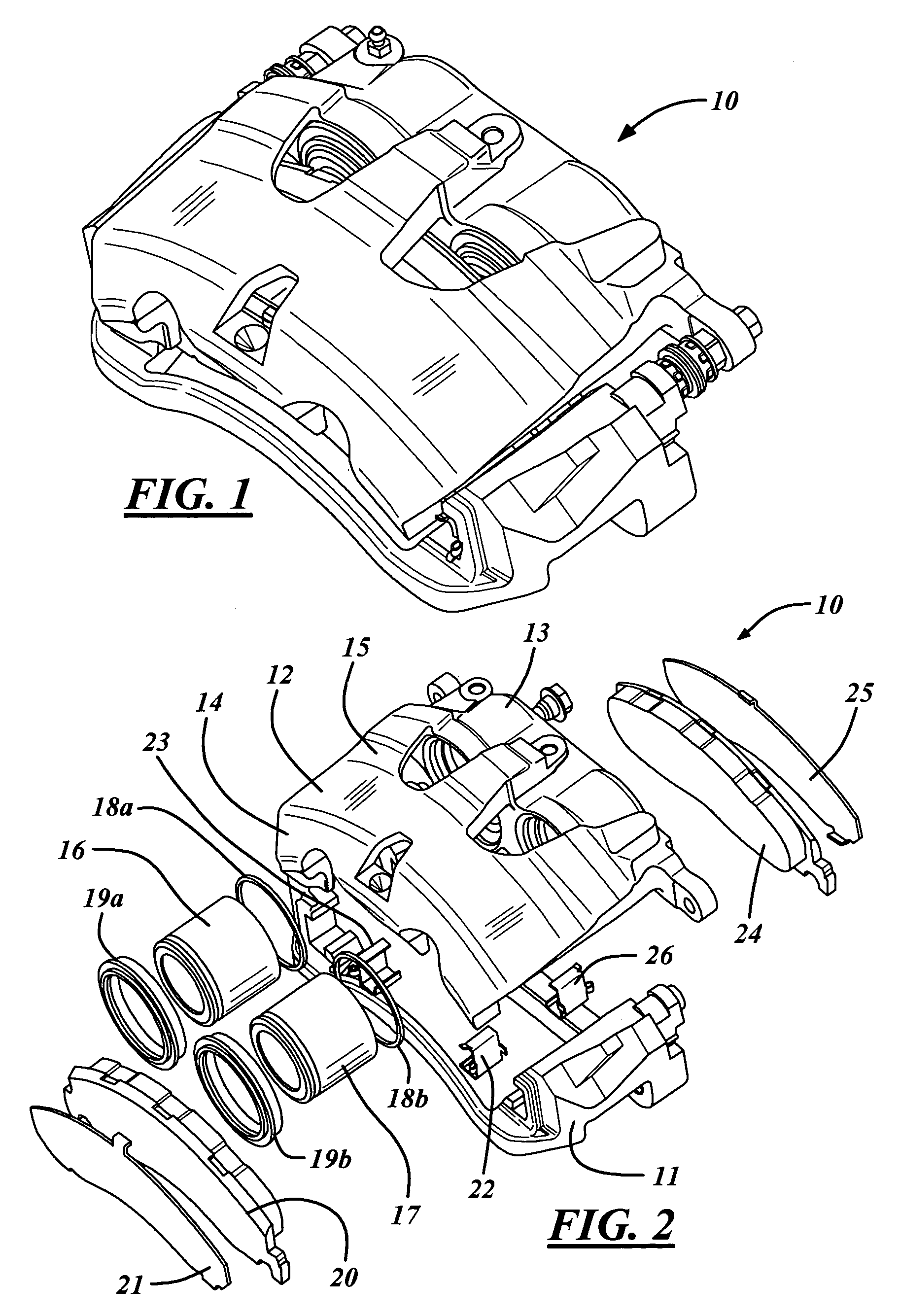
[0033]Referring now to the drawings, there is illustrated in FIG. 1 a disc brake assembly, shown generally at 10, for applying braking friction to a braking rotor (not shown) of a vehicle (not shown).

[0034]FIG. 2 illustrates an exploded view of the disc brake assembly 10. The disc brake assembly 10 includes an anchor plate 11 and a caliper 12. The caliper includes an inner leg portion 13 and an outer leg portion 14 connected by a bridge section 15. A pair of hydraulic actuators, namely a first piston 16 and a second piston 17 connect to hydraulic ports (not shown) of the inner leg portion 13. Alternatively, the disc brake assembly may include a single piston caliper, a single opposed caliper, a dual fixed opposed caliper, or two or more piston calipers of varying configurations may be utilized.

[0035]A first seal 18a and a second seal 18b are disposed between the first piston 16 and the second piston 17 and the respective hydraulic ports, respectively, for creating a sealed surface b...


PUM


Abstract

A brake pad assembly includes a brake pad including a base portion, a first ear portion, and an opposed second ear portion. The first ear portion and the second ear portion extend outwardly from the base section. The first ear portion includes a first upper section, a first central section, and a first lower section. The second ear portion includes a second upper section, a second central section, and a second lower section. A first clip receives the first ear portion and a second clip receives the second ear portion. The first ear portion includes a first defined contact location and a second defined contact location in relation to the first clip. The second ear portion includes a third defined contact location in relation to the second clip.

Description

CROSS-REFERENCE TO RELATED APPLICATIONS[0001]Not ApplicableSTATEMENT REGARDING FEDERALLY SPONSORED RESEARCH OR DEVELOPMENT[0002]Not ApplicableREFERENCE TO A SEQUENCE LISTING, A TABLE, OR A COMPUTER PROGRAM LISTING COMPACT DISC APPENDIX[0003]Not ApplicableBACKGROUND OF THE INVENTION[0004]1. Field of the Invention[0005]This invention relates in general to vehicle brakes and in particular to a brake pad having defined abutment contact points.[0006]2. Description of the Related Art[0007]Most vehicles are equipped with a brake system for slowing or stopping movement of the vehicle in a controlled manner. A typical brake system for an automobile or light truck includes a disc brake assembly for each of the front wheels and either a drum brake assembly or a disc brake assembly for each of the rear wheels. The brake assemblies are actuated by hydraulic or pneumatic pressure generated when an operator of the vehicle depresses a brake pedal. The structures of these drum brake assemblies and d...

Claims


Application Information

Patent Timeline
Patent Type & Authority Patents(United States)
IPC IPC(8): F16D65/02
CPCF16D65/0972F16D65/0977
Inventor FRANZ, SCOTTGIACOMAZZA, CHARLES C.MORAIS, EDUARDOVANDER ROEST, WILLIAM J.
Owner KELSEY HAYES CO
Why Eureka
Try Eureka