
Door closer

Inactive Publication Date: 2010-09-07
NHK SPRING CO LTD
View PDF11 Cites 0 Cited by
  • Summary
  • Abstract
  • Description
  • Claims
  • Application Information

AI Technical Summary

Benefits of technology

[0017]According to the invention there is inside a single case both a door-opening-assistance device that provides a door-opening force that can be used to counter the door closer's door-closing force and a closer that moves the door in the closing direction and provides force that is used to close the door. Therefore, an entire door closer assembly that combines a closer and a door-opening-assistance device can be made compact and improved in appearance. Also, the door-opening-assistance device and the closer are such that they work in connection with the opening of the door, and therefore, troublesome adjustment of the functioning of those two members is no longer necessary. In addition, the number of parts required is reduced, and therefore failure of the door closer occurs less frequently.
[0018]According to one aspect of the invention, the case is separated into a first chamber and a second chamber. Also, the closer is in the first chamber, and the door-opening-assistance device is in the second chamber—under the condition that first and second cylinder parts of the cylinder are connected with each other. Therefore, a change in the pressure in the first chamber does not influence the second chamber. Accordingly, the door-opening-assistance device in the second chamber is not influenced by the pressure in the first chamber, and therefore the door-opening-assistance device is capable of assisting the opening of the door smoothly and surely.

Problems solved by technology

Also, the door-opening-assistance device and the closer are such that they work in connection with the opening of the door, and therefore, troublesome adjustment of the functioning of those two members is no longer necessary.

Method used


Image

  • Door closer
  • Door closer
  • Door closer

Examples


Embodiment Construction

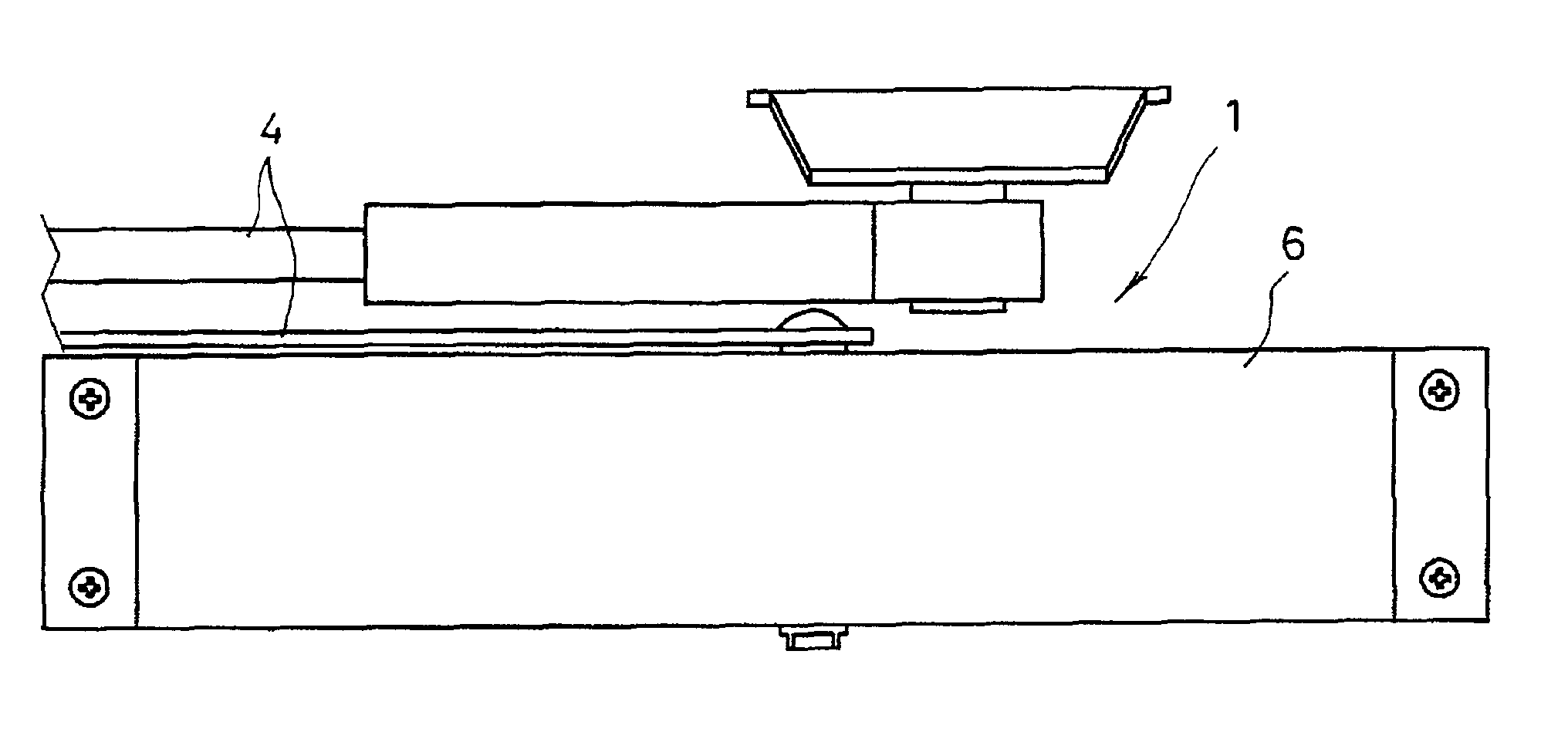
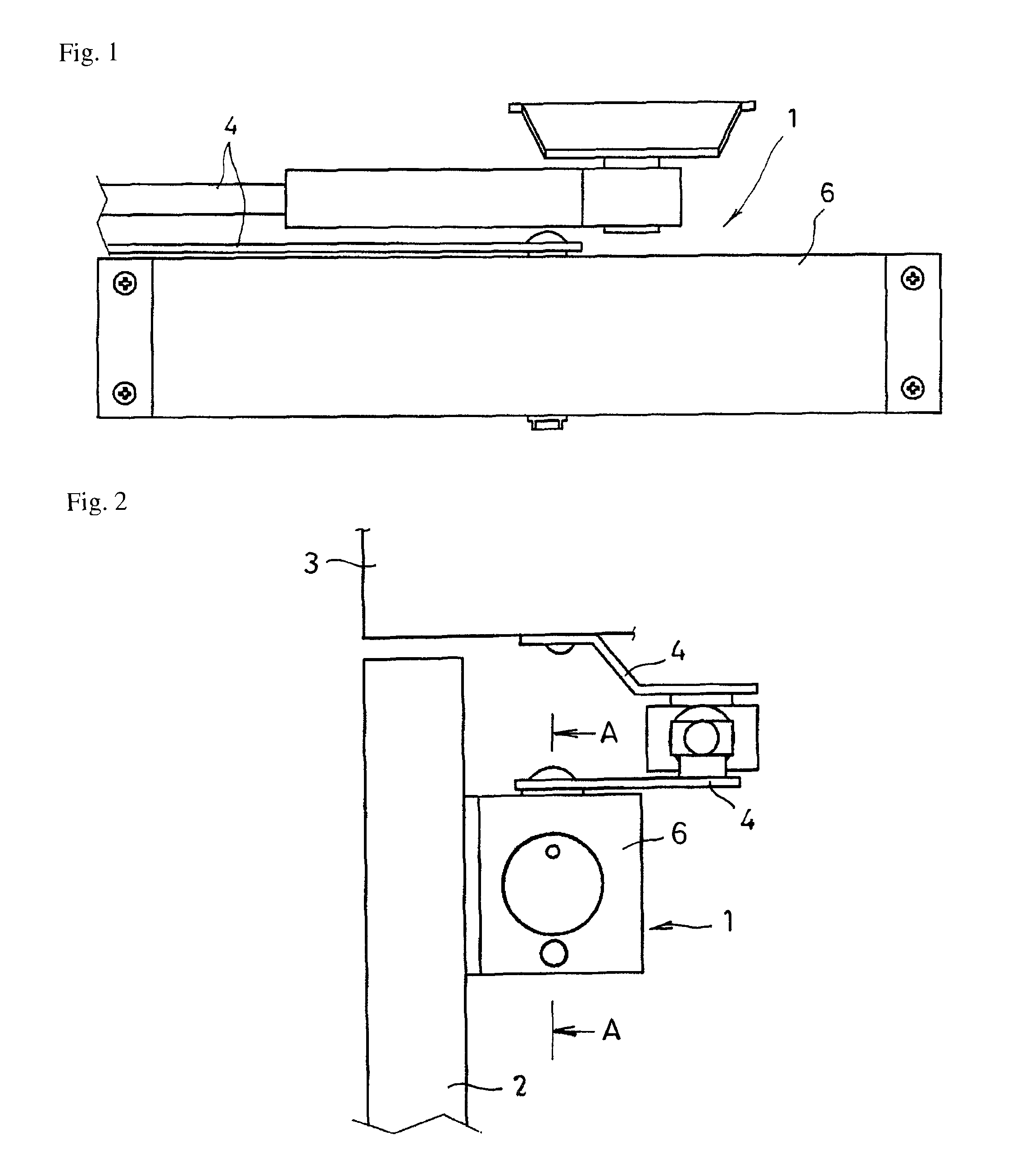
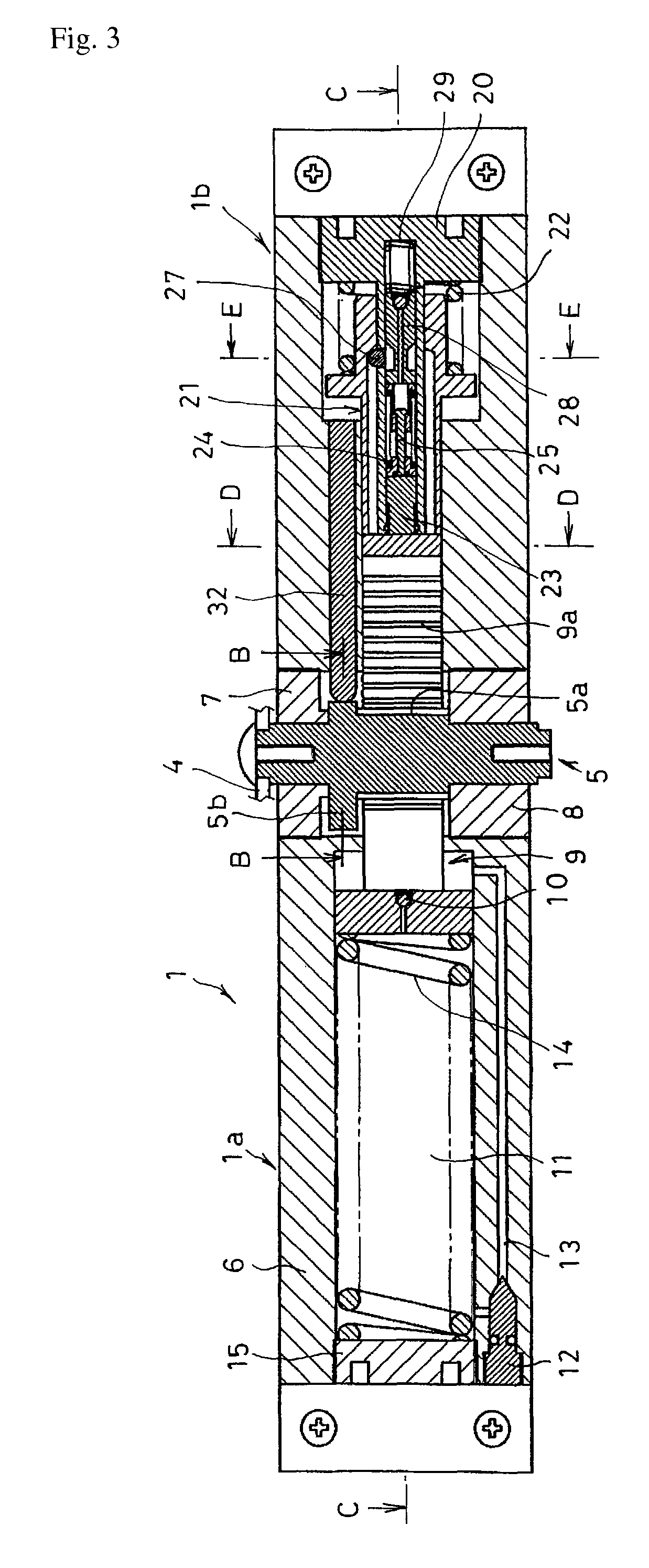
[0076]FIGS. 1 to 29 show one embodiment of the present invention. FIG. 1 is a front view of this embodiment; FIG. 2 is a left-side view of FIG. 1; FIG. 3 is a cross-sectional view along the line A-A of FIG. 2; FIG. 4 is a cross-sectional view along the line B-B of FIG. 3; FIG. 5 is a cross-sectional view along the line C-C of FIG. 3; FIG. 6 is a cross-sectional view along the line D-D of FIG. 3; FIG. 7 is a cross-sectional view along the line E-E of FIG. 3; FIG. 8 is a partial cross-sectional view of a locking mechanism and an unlocking mechanism; FIGS. 9 to 23 illustrate the actions of the door-opening-assistance device; and FIGS. 24 to 29 illustrate the actions of the unlocking spring and the locking spring corresponding to FIG. 8.

[0077]As shown in FIGS. 1 and 2, a door closer 1 in this embodiment is mounted, by using screws, at an upper part of a door 2 on the door's side that is inside a room or on the door's side that is outside the room, and is connected with a wall 3 via two ...


PUM


Abstract

A door closer that integrally incorporates a door-opening-assistance device, and that therefore eliminates the need for unnecessary troublesome adjustment between parts, and whose number of parts is reduced, making said door closer compact. The door closer 1 includes a closer 1a that includes a pinion 5 that rotates in the forward and reverse directions when the door is opened or closed, respectively. A cylinder 9 is meshed with the pinion 5 and moves forward and backward. A closing spring 14 energizes the door in the closing direction via the cylinder 9 and the pinion 5. A opening-assistance device 1b that includes an opening spring 22 that stores an opening force in the door-opening direction due to the movement of the cylinder 9 when the door is opened. Locking mechanisms 27, 28, and 29, that—when the door is opened—lock the opening spring 22 under an opening-force-storing condition. An unlocking mechanisms 23 and 24 that—when the door is closed—unlock the locking mechanisms. The closer 1a and the door-opening-assistance device 1b are inside the same case 6 and interlinked by the opening of the door.

Description

CROSS-REFERENCE TO RELATED APPLICATIONS[0001]The present Application is based on International Application No. PCT / JP2005 / 023085, filed on Dec. 15, 2005, which claims priority from Japan Application No. 2004-370254, filed Dec. 21, 2004 and Japan Application No. 2005-139135, filed on May 11, 2005, the disclosures of which are hereby incorporated by reference in their entirety into the present application.FIELD OF THE INVENTION[0002]The present invention relates to a door closer that provides force that is used to close the door, and more particularly relates to a door closer which is integrally assembled as an opening-assistance device that, when a person applies force on a door to open it, assists the user by giving additional force in the door-opening direction so that the opening of the door is facilitated.BACKGROUND OF THE INVENTION[0003]A door is provided with a door closer for surely closing the door. And in the case of either a building, such as a condominium building, that is...

Claims


Application Information

Patent Timeline
Patent Type & Authority Patents(United States)
IPC IPC(8): E05F1/08
CPCE05F3/102E05F3/223E05F3/224E05Y2201/41Y10T16/293E05Y2800/113E05Y2900/132Y10T16/577Y10T16/27E05Y2201/422
Inventor YAMAMURO, KOICHI
Owner NHK SPRING CO LTD
Learn More