
Piston actuated vapor-dispersing device

a vapor-dispersing device and piston-actuated technology, which is applied in the field of electronic vapor-dispersing devices, can solve the problems of large fiber wicks clogging, devices slowing down, and many limitations of such electronic devices, and achieve the effect of smoothing out the delivery of volatile liquid over tim

Inactive Publication Date: 2010-09-14
HENKEL KGAA
View PDF22 Cites 53 Cited by
  • Summary
  • Abstract
  • Description
  • Claims
  • Application Information

AI Technical Summary

Benefits of technology

This approach provides a more linear and controlled evaporation of volatile liquids, maintaining consistent fragrance delivery and preventing clogging, as the evaporative member is kept from complete saturation and the piston's motion ensures continuous air movement for vapor dispersal.

Problems solved by technology

In spite of the fact that fan, heater, fan plus heater, and piezoelectric air fresheners have dominated the marketplace over the last decade or so, there remain many limitations to such electronic devices.
Most problems relate to the fact that the wick is both the evaporation medium and the liquid transfer means and as the evaporation surface it either needs to be of a huge size (e.g., a thick fiber bundle) or heated by a proximate heating element.
Invariably these devices slow down since the porous wicks clog with the less volatile ingredients and the spectrum of fragrance notes changes throughout the lifetime of the device, particularly if the wick is comprised of a fiber bundle and used in association with an aqueous fragrance solution containing a surfactant.
In that instance, the large fiber wick will clog over time with the non-volatile surfactants and emulsifiers used to stabilize in the fragrance solution.
In the heated example, the saturated heated wick continually leaves behind dark yellow, non-volatile base notes, and the wick clogs with no further new surfaces and unclogged pores left to assist in evaporation.
Vapor-dispersing devices that contain pistons are extremely scant in the literature and are all based on movement of a piston to increase internal pressure within a reservoir to push liquid out.
None of these devices employ a moveable piston in a non-pressurized device for effecting the repeated touching of an evaporative member onto the end of a liquid transfer means such that volatile liquid is pulled from a reservoir and evaporated into the adjacent environment in a controlled manner.

Method used


Image

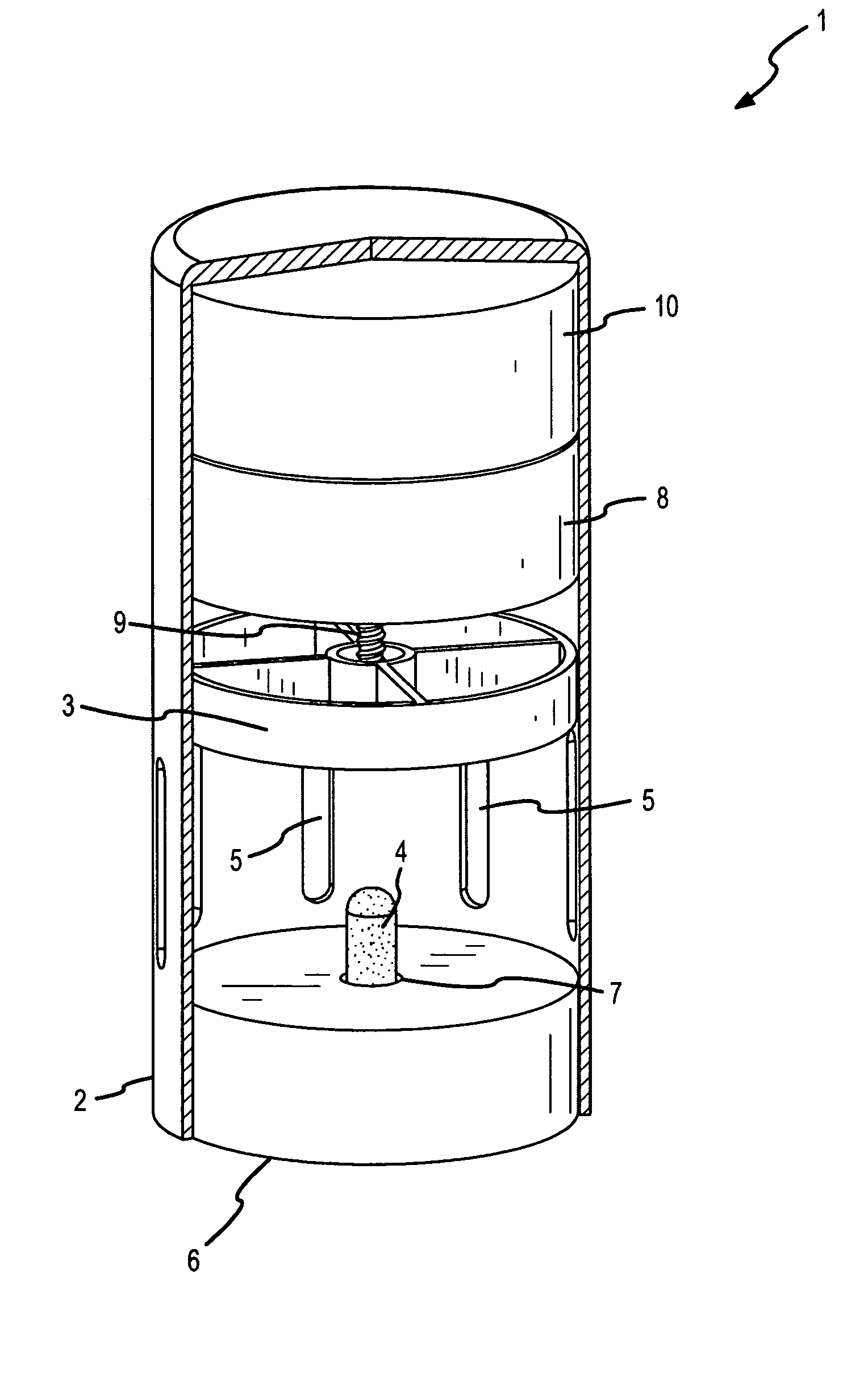
  • Piston actuated vapor-dispersing device
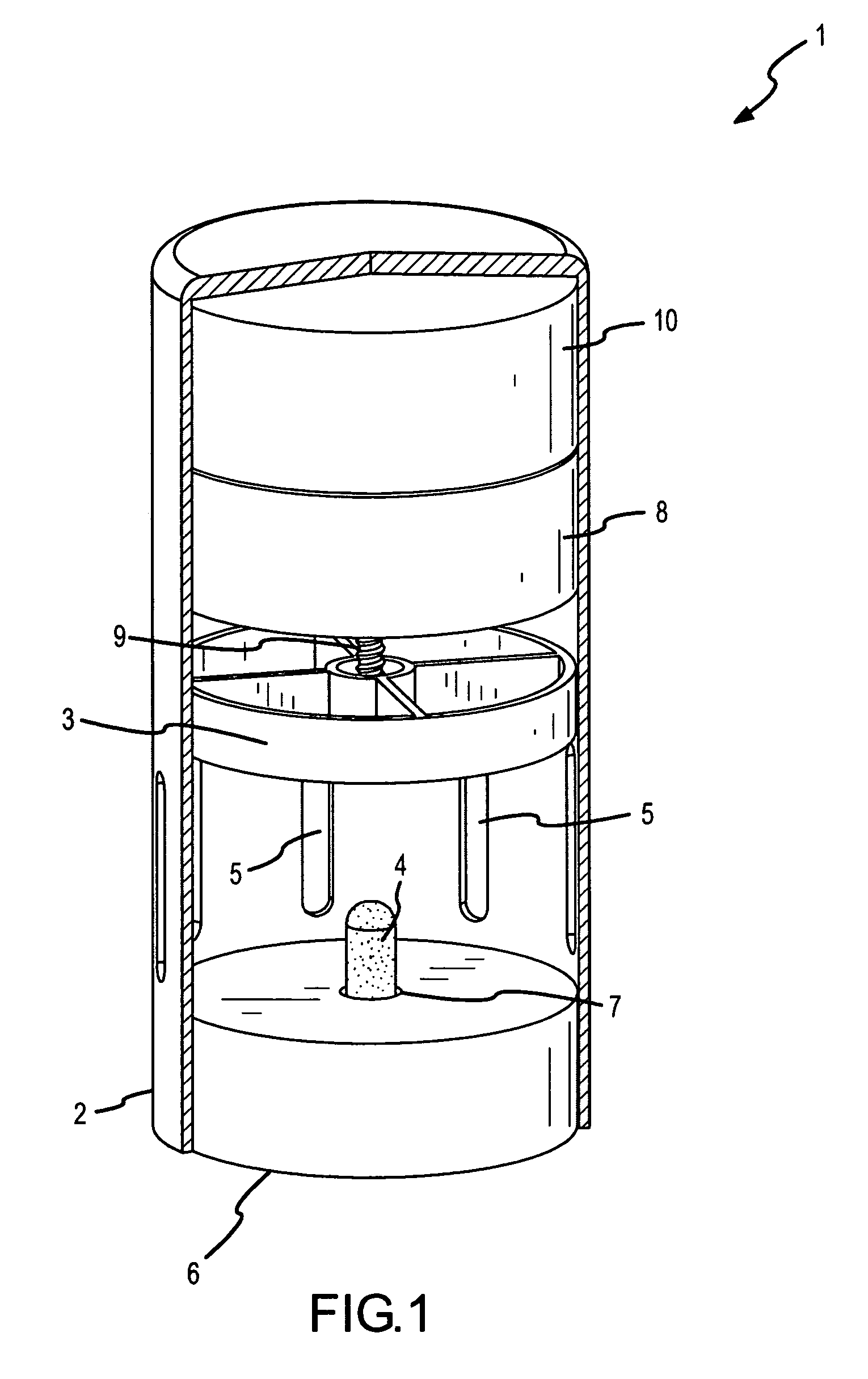
  • Piston actuated vapor-dispersing device
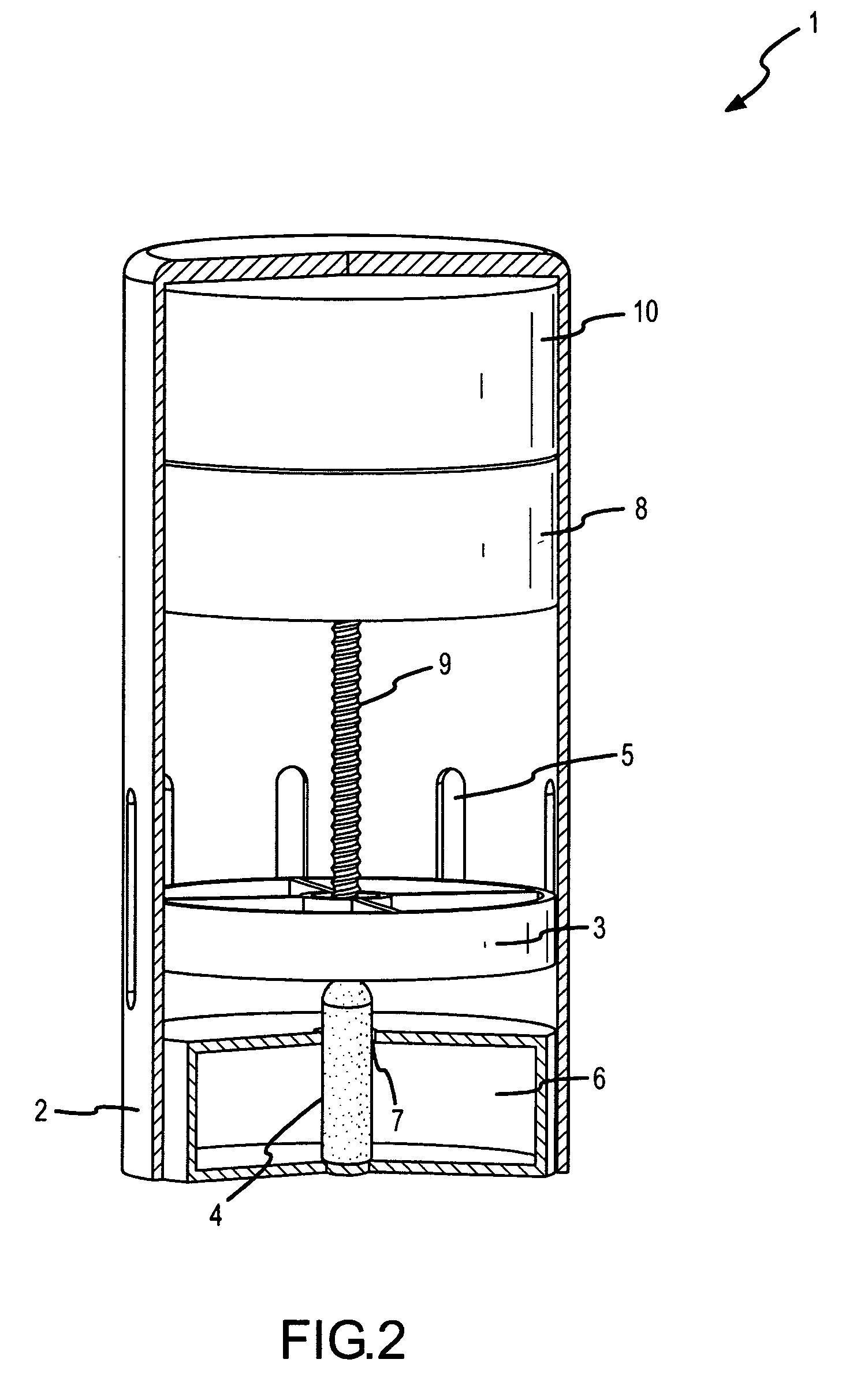
  • Piston actuated vapor-dispersing device

Examples


Embodiment Construction

[0021]The following description is of exemplary embodiments only and is not intended to limit the scope, applicability or configuration of the invention in any way. Rather, the following description provides a convenient illustration for implementing exemplary embodiments of the invention. Various changes to the described embodiments may be made in the function, the size, and arrangement of the elements described without departing from the scope of the invention as set forth in the appended claims. Most importantly, changes in shape and size of the overall device do not depart from the intended scope of the invention.

[0022]That said, the present invention relates to a piston-actuated electromechanical vapor-dispersing device that shows a more linear evaporation of volatile liquid than conventional electrical devices utilizing heater and / or fan elements or passive devices with large cotton or fiber wicks.

[0023]The present invention relates to a device that minimally comprises a housi...


PUM

PropertyMeasurementUnit
heightaaaaaaaaaa
diameteraaaaaaaaaa
heightaaaaaaaaaa

Abstract

A vapor-dispersing device comprising a moveable piston with an evaporative member is described that operates by the repetitive movement of the piston to bring the evaporative member into repeated contact with the exposed end of a liquid transfer means to wick volatile liquid out from a reservoir onto the evaporative member and to expel vapors out through vents.

Description

FIELD OF INVENTION[0001]The present invention relates to electromechanical vapor-dispersing devices and in particular to a vapor-dispersing device with a moveable piston that repeatedly brings an evaporative member such as a porous pad into contact with the end of a liquid transfer means placed within a reservoir and in communication with a volatile liquid. Upon contact with the liquid transfer means, the evaporative member draws up the liquid from the reservoir and moves air around via a bellows effect that evaporates the volatile liquid from the device into the adjacent environment in a linear and controlled manner.BACKGROUND[0002]Vapor-dispersing devices are well known and include a variety of devices for vaporizing a liquid such as a perfume or insecticide into the surrounding environment. For example, vapor-dispersing devices include electrical devices with resistive heater modules and / or fans for driving liquids into the vapor phase, passive devices that rely on pads, wicks, o...

Claims


Application Information

Patent Timeline
Patent Type & Authority Patents(United States)
IPC IPC(8): A24F25/00B65D85/00B67B7/00B65B53/00A62C13/62B65D69/00A61L9/04B67D7/08B67D7/00B05B9/00B05B1/08
CPCA01M1/2044A61L9/127Y10T428/1328
Inventor BANKERS, JEFFREYHAFER, KEVIN
Owner HENKEL KGAA
Learn More