

Centrifugal fan and apparatus using the same
a centrifugal fan and centrifugal fan technology, applied in the direction of liquid fuel engines, vessel construction, marine propulsion, etc., can solve the problems of turbulent flow noise, reduced total pressure efficiency, and tend to occur at the dorsal side of the blades
- Summary
- Abstract
- Description
- Claims
- Application Information
AI Technical Summary
Benefits of technology
Problems solved by technology
Method used
Image

Examples
first exemplary embodiment
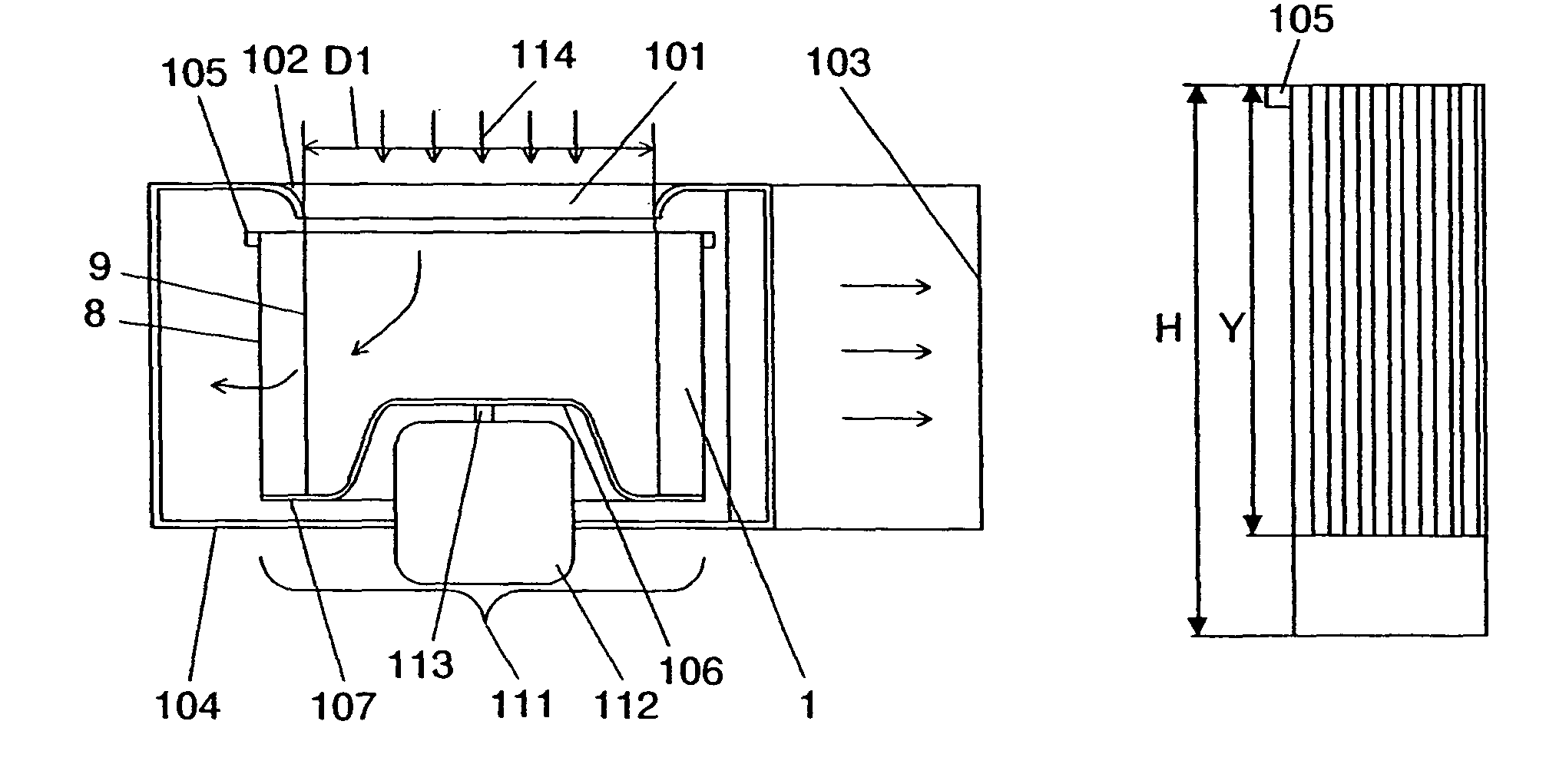
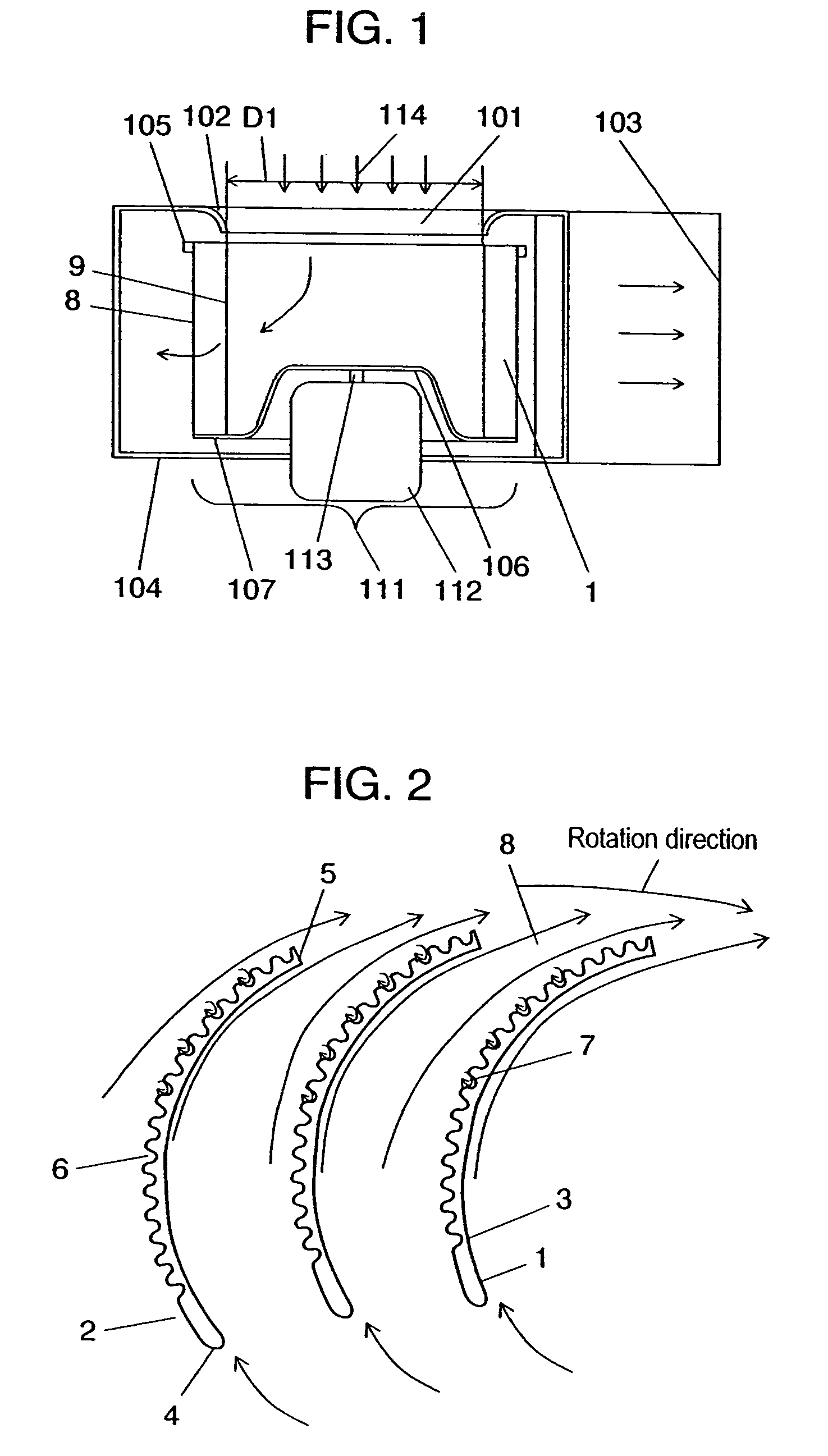
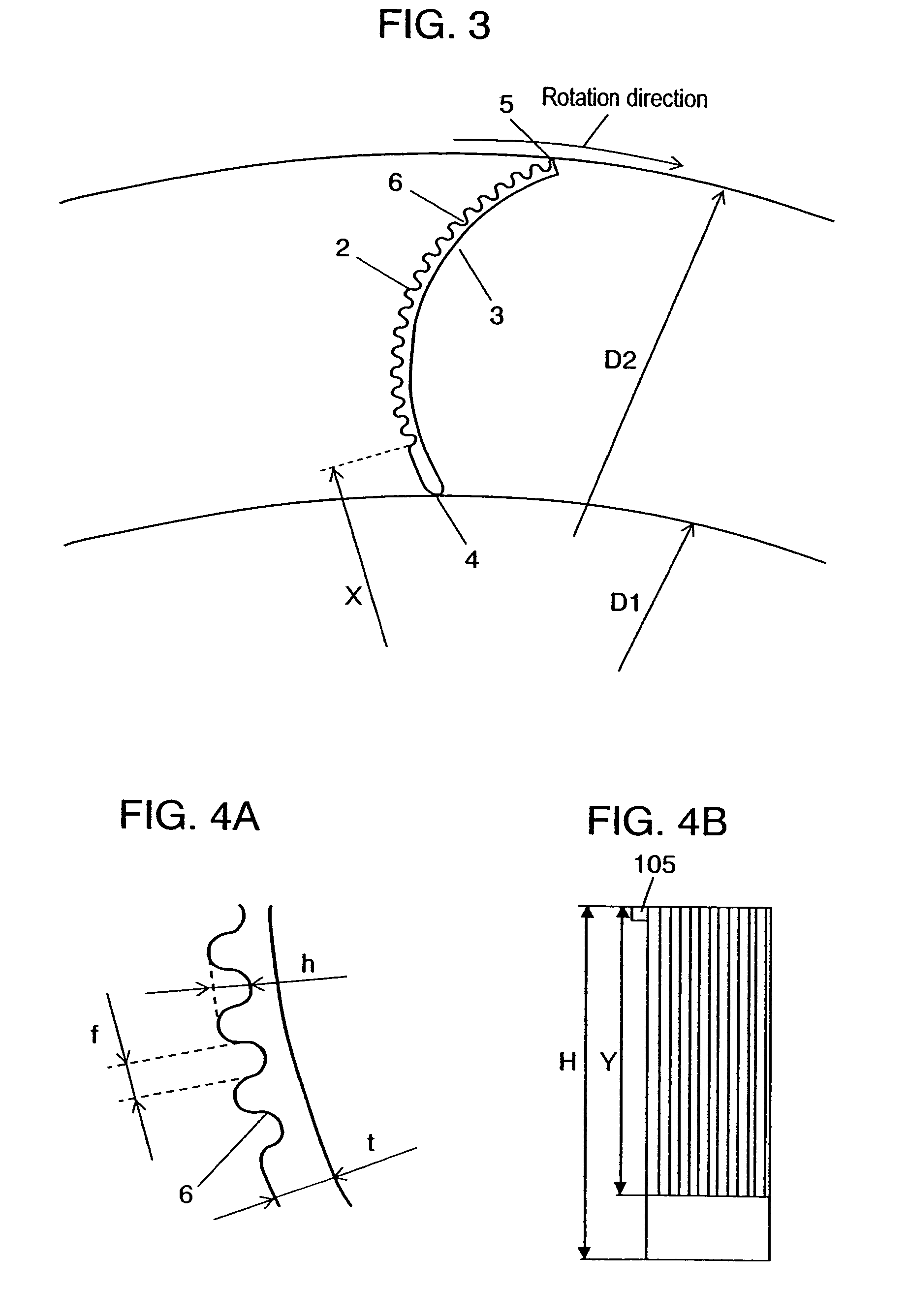
[0057]FIG. 1 is a sectional side view of the centrifugal fan and casing according to the first exemplary embodiment of the present invention. FIG. 2 illustrates a cross section of blades of the centrifugal fan, taken along a line vertical to the rotation axis, along with the airflow. FIGS. 3, 4A, and 4B illustrate the specifications of the shape of the asperities provided on a blade. FIGS. 5A and 5B illustrate the installation mode and specifications of the asperities, in the axial direction. FIGS. 6A through 6G illustrate types of the shape of the asperities provided on a blade. FIGS. 7 and 8 illustrate a performance characteristic in this embodiment.
[0058]As shown in the figure, spiral casing 104 is formed at its one side with bellmouth-like inlet 101, and has orifice 102 with the same internal diameter as blade internal diameter D1 and discharge outlet 103. This casing 104 is provided therein with ring-like lateral plate 105, and main plate 107 having throttle 106 substantially t...
second exemplary embodiment
[0070]FIG. 9 illustrates a cross section of the centrifugal fan according to the second exemplary embodiment of the present invention, taken along a line vertical to the rotation axis of a blade, along with the airflow. FIGS. 10, 11A, and 11B illustrate the specifications of the shape of the asperities provided on a blade. FIGS. 12A and 12B illustrate the installation mode and specifications of the asperities in the axial direction. FIGS. 13A through 13G illustrate types of the shape of the asperities provided on a blade.
[0071]In this embodiment, for a component with a makeup same as that in the above-mentioned exemplary embodiment, the same mark is given to omit its description. This embodiment is different from the first exemplary embodiment in the shape of blades.
[0072]As shown in FIG. 9, blade 1 in this embodiment, unlike the first exemplary embodiment, is formed with a plurality of asperities 6 at ventral blade side 3 from front blade edge 4 toward rear blade edge 5. Such a mak...
third exemplary embodiment
[0081]This embodiment is the same as the first and second exemplary embodiments except that asperities are formed at both dorsal blade side 2 and ventral blade side 3 of blade 1.
[0082]More specifically, an asperities is formed at dorsal blade side 2 of blade 1, in the same way as in the first exemplary embodiment; and ventral blade side 3, as in the second exemplary embodiment.
[0083]In the large air volume and low static pressure zone, development of a boundary layer occurring between blades, which is caused by microscopic eddies 7 occurring on asperities 6 at blade ventral side 2 and blade dorsal side 1, can be suppressed. Further, reattaching airflow that has exfoliated from blade 1 allows turbulence from blade outlet 8 to be minimized.
[0084]In the low air volume and high static pressure zone, exfoliation of airflow from blade inlet 9 and development of a boundary layer are suppressed to minimize turbulence from blade outlet 8.
Forth Exemplary Embodiment
[0085]FIG. 14 is a sectional...
PUM
 Abstract
Description
Claims
Application Information