Optical head with diffuser structure
a technology of optical head and diffuser, which is applied in the field of optical head having a diffuser structure, can solve the problems of ineffective increase of illumination efficiency, ineffective widening of the allowable range of tilt angle, and inability to reduce usage and power consumption of leds, so as to enhance illumination efficiency, broaden the allowable range of tilt angle, and eliminate dead spots of recognition
- Summary
- Abstract
- Description
- Claims
- Application Information
AI Technical Summary
Benefits of technology
Problems solved by technology
Method used
Image
Examples
first embodiment
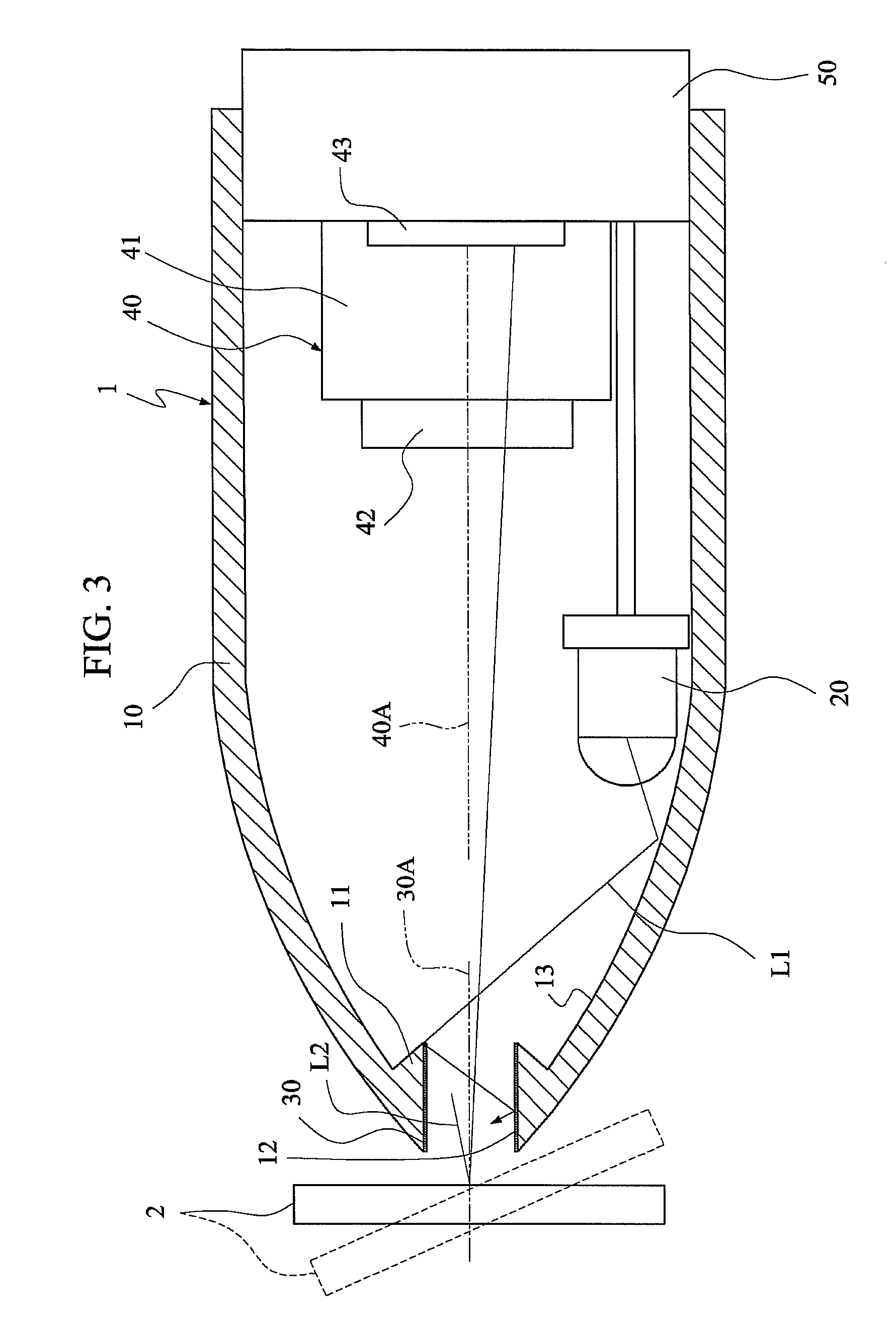
[0024]FIG. 3 is a schematic illustration showing application of an optical head 1 according to a first embodiment of the invention. Referring to FIG. 3, the optical head 1 for reading an object 2, such as an e-book, on which two-dimensional bar code patterns are printed, includes a hollow housing 10, a light source module 20, a diffuser structure 30 and a light sensing module 40.
[0025]The light source module 20 is fixed in the hollow housing 10 and provides an initial light ray L1. The light source module 20 includes, without limitation to, a light-emitting diode (LED) or multiple LEDs. The LEDs may output the same light ray or different light rays. In this embodiment, an LED is provided as an example, and the initial light ray L1 is reflected from an inner wall surface 13 of the hollow housing 10 to the diffuser structure 30. However, the initial light ray L1 may also be directly incident to the diffuser structure 30.
[0026]The diffuser structure 30 connected to the hollow housing 1...
second embodiment
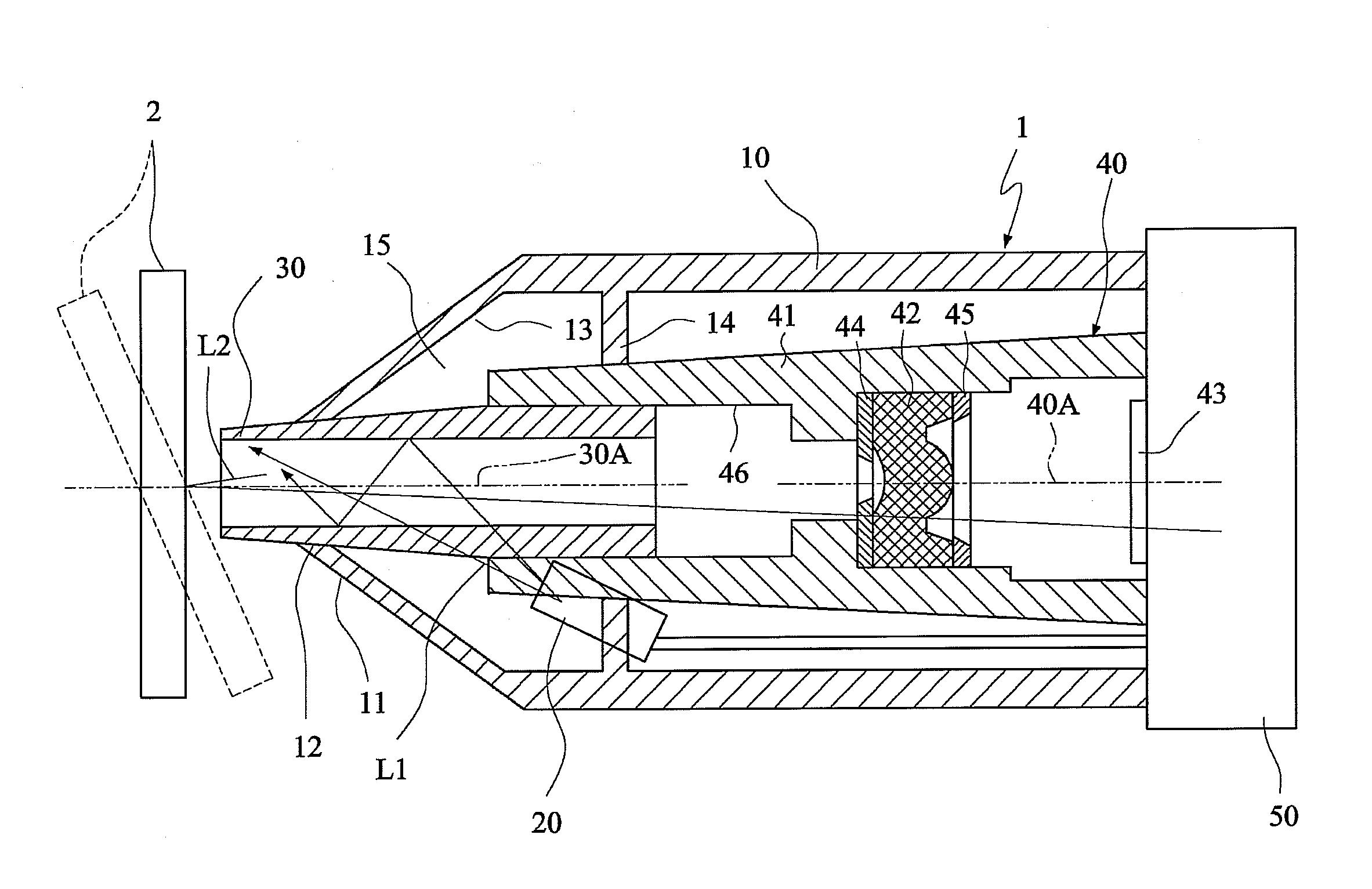
[0030]In this embodiment, a tube-like diffuser structure is used to provide the homogenized light ray.
[0031]FIG. 4 is a schematic illustration showing application of an optical head according to a second embodiment of the invention. As shown in FIG. 4, the optical head of this embodiment is similar to the first embodiment except that the diffuser structure 30 is a hollow tube mounted on the opening 11 of the hollow housing 10. Thus, the initial light ray L1 is refracted through the diffuser structure 30 and then reflected in the diffuser structure 30. It is to be noted that the diffuser structure 30 may be a solid cylinder, which is advantageous to the isolation of the external dust from the light sensing module 40. Alternatively, the diffuser structure 30 may be composed of the hollow tube and a transparent member for sealing the hollow tube.
[0032]In addition, it is also possible to design the diffuser structure 30 to be slidable relative to the hollow housing 10 in this embodiment...
third embodiment
[0033]In this embodiment, a tube-like diffuser structure is used in conjunction with a light integrating structure to provide the homogenized light ray.
[0034]FIG. 5 is a schematic illustration showing application of an optical head according to a third embodiment of the invention. As shown in FIG. 5, the optical head of this embodiment is similar to the first embodiment except that the diffuser structure 30 is mounted on the opening 11 of the hollow housing 10 and an inner stopper edge 14 of the hollow housing 10. Therefore, the diffuser structure 30, the hollow housing 10 and the inner stopper edge 14 may form an airtight space 15 serving as a light integrating structure so that the much more homogenized light ray can be provided in conjunction with the diffuser structure 30.
[0035]In this embodiment, the LED of the light source module 20 is disposed in the airtight space 15, and the initial light ray L1 is first refracted through the diffuser structure 30 and then reflected in the ...
PUM
| Property | Measurement | Unit |
|---|---|---|
| wavelength | aaaaa | aaaaa |
| depth of field | aaaaa | aaaaa |
| tilt angle | aaaaa | aaaaa |
Abstract
Description
Claims
Application Information
 - R&D
- Intellectual Property
- Life Sciences
- Materials
- Tech Scout
- Unparalleled Data Quality
- Higher Quality Content
- 60% Fewer Hallucinations
Browse by: Latest US Patents, China's latest patents, Technical Efficacy Thesaurus, Application Domain, Technology Topic, Popular Technical Reports.
© 2025 PatSnap. All rights reserved.Legal|Privacy policy|Modern Slavery Act Transparency Statement|Sitemap|About US| Contact US: help@patsnap.com


