
Optical head that can be easily assembled

a head and optical technology, applied in the field of optical heads, can solve the problems of ineffective increase of illumination efficiency, ineffective widening of the allowable tilt angle range, and inability to reduce the usage and power consumption of leds, so as to eliminate the dead spot of recognition, facilitate assembly, and enhance illumination efficiency

Inactive Publication Date: 2010-01-14
SUNPLUS MMEDIA
View PDF1 Cites 2 Cited by
  • Summary
  • Abstract
  • Description
  • Claims
  • Application Information

AI Technical Summary

Benefits of technology

[0012]It is therefore an object of the invention to provide an optical head that can be easily assembled, can eliminate the dead spot of recognition caused by the strong reflected light, can enhance the illumination efficiency to reduce the number and the power consumption of light sources, and can enhance the illumination uniformity to enhance the allowable range of a tilt angle.
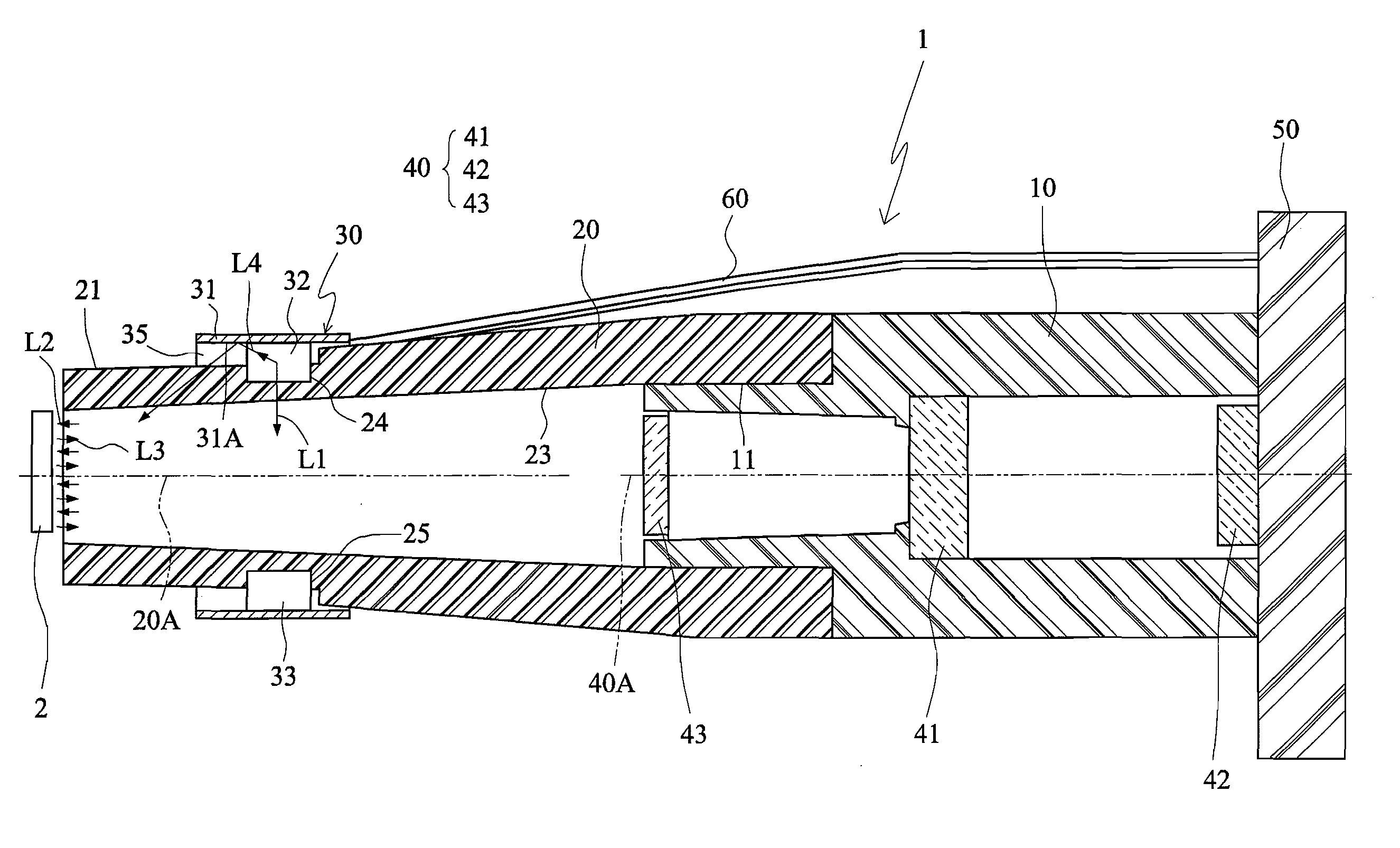
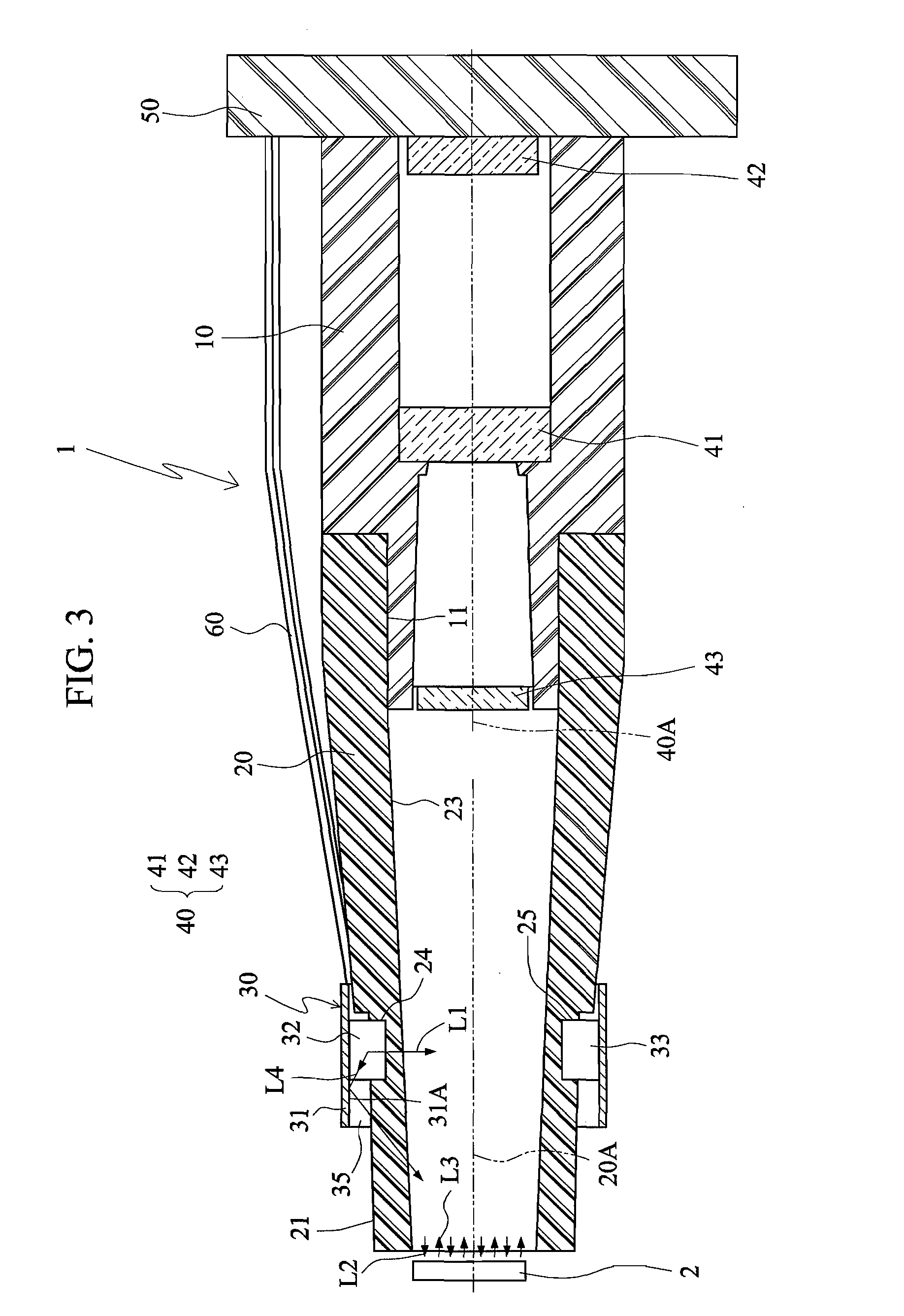
[0013]To achieve the above-identified object, the invention provides an optical head, which can be easily assembled and is for reading an image of an object. The optical head includes a housing, a diffuser, a light source module and a light sensing module. The diffuser is connected to the housing. The light source module has a substrate and a first light source mounted on a front side of the substrate. The front side of the substrate is fixed to an external surface of the diffuser. The first light source provides an initial light ray incident to the diffuser, and the diffuser processes the initial light ray into uniform light for output. The light sensing module fixed in the housing is for sensing reflected light generated from the uniform light reflected by the object.
[0014]Thus, the size of the optical head can be significantly reduced so that the user can carry the optical head conveniently. In addition, the light source may be disposed at a location very close to the to-be-measured object, and most light rays outputted from the light source may be incident to the diffuser substantially vertically, so the illumination efficiency and the recognition ability can be effectively enhanced. Furthermore, the LED may be directly bonded to the flexible circuit board so that the so-called surface mount LED is obtained and the light source module may be mounted more simply because the flexible circuit board only needs to surround the diffuser over 360 degrees. Thus, the optical head can be easily assembled.

Problems solved by technology

Consequently, the drawback of the conventional optical head is that the dead spots of recognition caused by the reflected strong light cannot be eliminated so that the illumination efficiency cannot be effectively increased, the usage and power consumption of the LED cannot be decreased, and the allowable range of the tilt angle cannot be effectively broadened.
In addition, the fabrication of the conventional optical head is also very complicated.

Method used


Image

  • Optical head that can be easily assembled
  • Optical head that can be easily assembled
  • Optical head that can be easily assembled

Examples


Embodiment Construction

[0021]The present invention will be apparent from the following detailed description, which proceeds with reference to the accompanying drawings, wherein the same references relate to the same elements.

[0022]FIG. 3 is a schematic illustration showing application of an optical head 1 according to a first embodiment of the invention. Referring to FIG. 3, the optical head 1 of this embodiment is for reading an image of an object 2. The object 2 may be, for example, an e-book, on which patterns of two-dimensional bar codes are printed. The optical head 1 includes a housing 10, a diffuser 20, a light source module 30 and a light sensing module 40.

[0023]The diffuser 20 is connected to the housing 10. In FIG. 3, the diffuser 20 may be a hollow body or a hollow tube and may serve as a light integrating sphere. However, the diffuser 20 may also be a solid body or a solid cylinder. The diffuser 20 may have a circular cross-sectional shape, a rectangular cross-sectional shape or other cross-se...


PUM


Abstract

An optical head that can be easily assembled is for reading an image of an object and includes a housing, a diffuser, a light source module and a light sensing module. The diffuser is connected to the housing. The light source module has a substrate and a first light source mounted on a front side of the substrate. The front side of the substrate is fixed to an external surface of the diffuser. The first light source provides an initial light ray incident to the diffuser. The diffuser processes the initial light ray into uniform light for output. The light sensing module fixed in the housing senses reflected light, which is generated from the uniform light reflected by the object.

Description

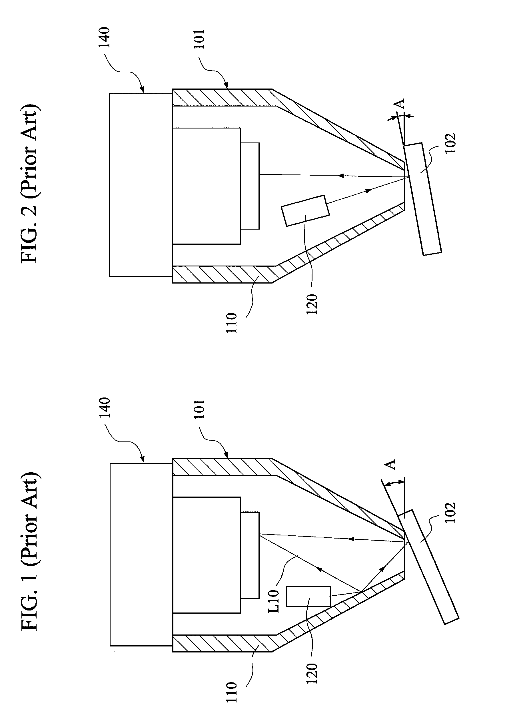
[0001]This application claims priority of No. 097126009 filed in Taiwan R.O.C. on Jul. 10, 2008 under 35 USC 119, the entire content of which is hereby incorporated by reference.BACKGROUND OF THE INVENTION[0002]1. Field of Invention[0003]The invention relates to an optical head that can be easily assembled.[0004]2. Related Art[0005]FIG. 1 is a schematic illustration showing application of a conventional optical head 101. Referring to FIG. 1, the optical head 101 for reading an object 102 includes a hollow housing 110, a light source module 120 and a light sensing module 140. The light source module 120 is fixed in the hollow housing 110 and provides a light ray. The light ray is reflected in the hollow housing 110 and then illuminates the object 102. The light sensing module 140 fixed in the hollow housing 110 senses the light ray reflected by the object 102.[0006]The light ray reflection may include specular reflection, spread reflection and diffuse reflection. The specular reflect...

Claims


Application Information

Patent Timeline
Patent Type & Authority Applications(United States)
IPC IPC(8): H01J3/14
CPCG02B13/00
Inventor WU, CHIH MANG
Owner SUNPLUS MMEDIA
Learn More