Motor drive with VAR compensation

a technology of var compensation and motor drive, which is applied in the direction of electric variable regulation, process and machine control, instruments, etc., can solve the problems of space occupation of devices and add to the cost of operating the overall system

Active Publication Date: 2010-09-21
ROCKWELL AUTOMATION TECH
View PDF18 Cites 26 Cited by
  • Summary
  • Abstract
  • Description
  • Claims
  • Application Information

AI Technical Summary

Benefits of technology

[0004]In accordance with one or more aspects of the present disclosure, an AC motor drive is provided, which includes an input and a motor load output, an intermediate circuit with capacitive and / or inductive storage element(s), a line side switching converter connected between the input and the intermediate source, and a machine or load side switching converter between the intermediate circuit and the output. The switches of the line and machine side converters are controlled according to switching signals generated by a dual mode switch control system of the drive which operates in a first mode to drive the motor load according to a motor drive control scheme and in a second mode to perform VAR compensation of the power system at large with the motor stopped. In the VAR control mode, the control system provides machine side switching control signals to prevent power transfer between the intermediate circuit and the output, and generates line side switching control signals to selectively couple the input to the intermediate circuit according to a VAR compensation scheme.

Problems solved by technology

In such systems, however, there are multiple loads connected to the common power connection, and the system as a whole will often not be operating at or near unity power factor, even of the motor drives themselves are power factor corrected.
However, these devices occupy space and add to the cost of operating the overall system.

Method used


Image

  • Motor drive with VAR compensation
  • Motor drive with VAR compensation
  • Motor drive with VAR compensation

Examples


Embodiment Construction

[0020]Referring now to the figures, several embodiments or implementations of the present invention are hereinafter described in conjunction with the drawings, wherein like reference numerals are used to refer to like elements throughout, and wherein the various features are not necessarily drawn to scale.

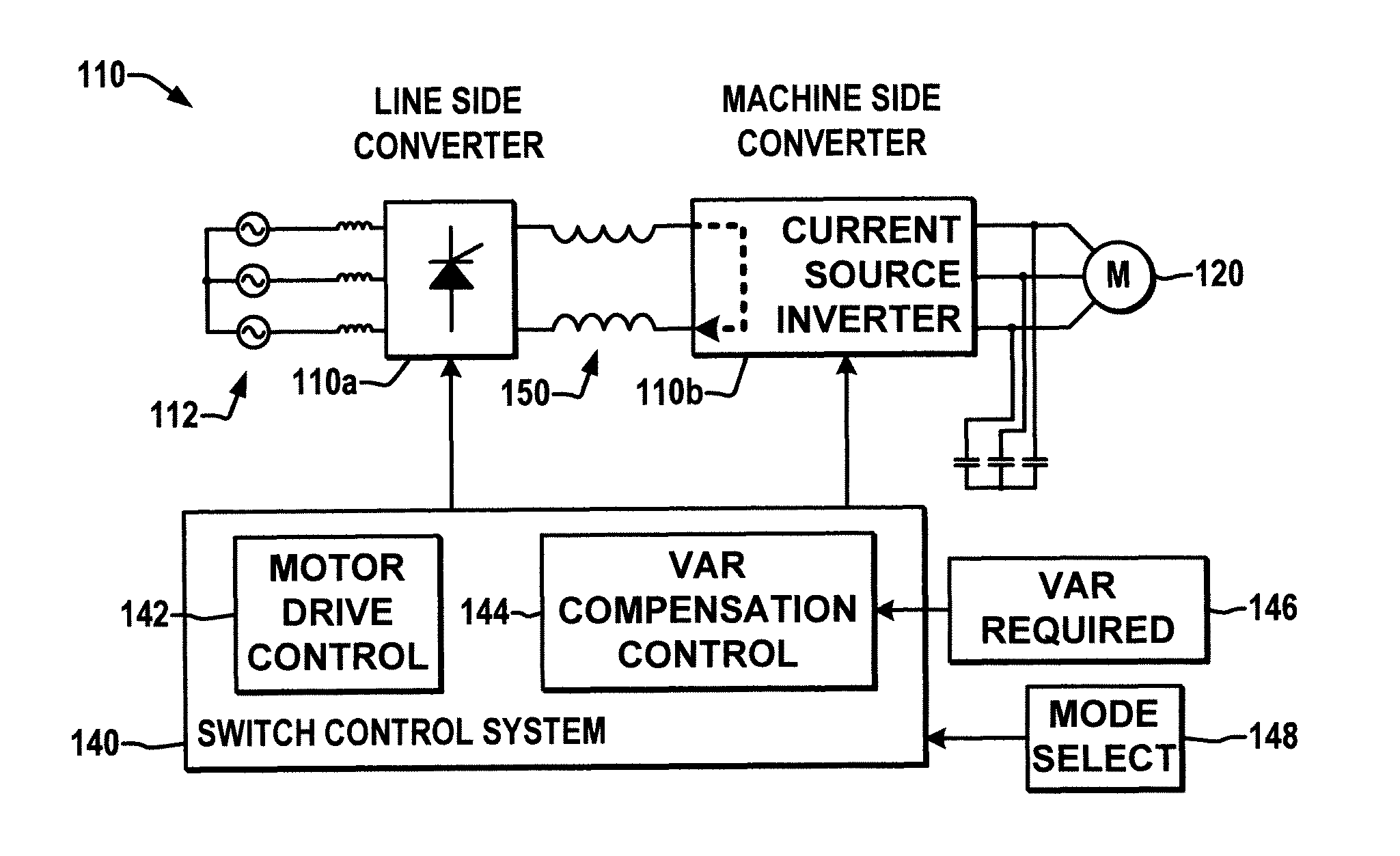
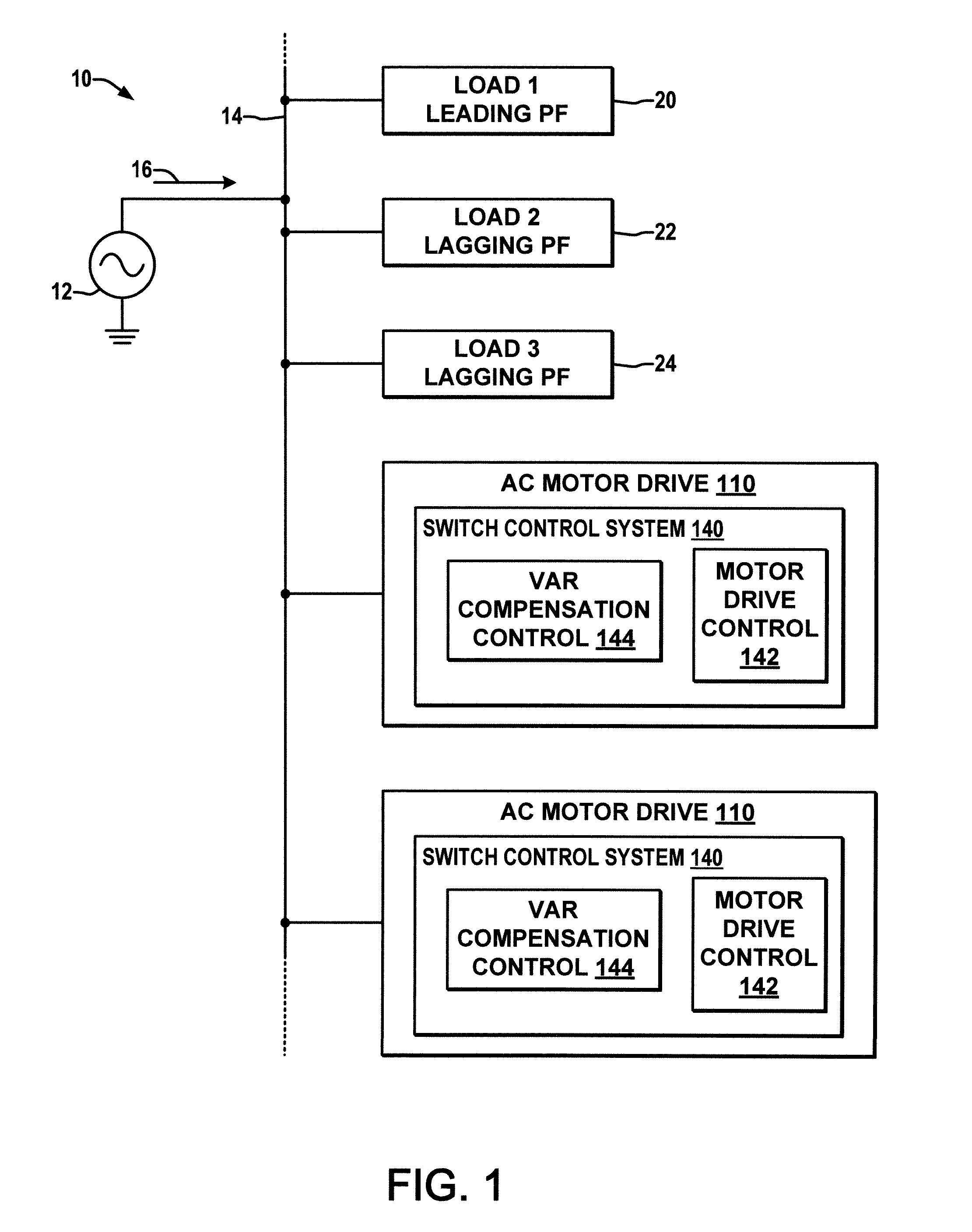
[0021]FIG. 1 shows a power system 10 in which AC motor drives 110 are connected to an AC power bus or point of common coupling 14 along with other loads 20, 22, 24, where an AC power source 12 provides current 16 to the common bus 14. The motor drives 110 may be equipped with power factor correction (PFC) apparatus to operate the drive when controlling the associated motor at or near unity power factor. However, the source 12 powers other AC loads 20, 22, and 24 via the common power connection 14, and absent countermeasures the system 10 as a whole will often not be operating at or near unity power factor. For instance, the first load 20 may be operating at a leading factor while o...


PUM


Abstract

Apparatus and methods are disclosed for providing VAR compensation using an AC motor drive, in which an off-line motor drive is configured to prevent power transfer to a motor load output, with a line side converter being operated to control a voltage or current in an intermediate circuit for leading or lagging VAR compensation of an AC power system.

Description

FIELD OF THE INVENTION[0001]The present invention relates generally to electrical power conversion and more particularly to motor drives with VAR compensation capabilities.BACKGROUND OF THE INVENTION[0002]Power conversion systems convert electrical power from one form to another and may be employed in a variety of applications such as motor drives for powering an electric motor using power from an input source. Typically, the power converter is constructed using electrical switches actuated in a controlled fashion to selectively convert input power to output power of a desired form such as single or multi-phase AC of a controlled amplitude, frequency and phase to drive an AC motor according to a desired speed and / or torque profile, often in the presence of varying load conditions. In a typical situation, one or more AC motor drives are connected to an AC power bus or point of common coupling along with other loads where a common AC power source provides current to all these loads vi...

Claims


Application Information

Patent Timeline
Patent Type & Authority Patents(United States)
IPC IPC(8): G05F1/70
CPCH02M5/4585H02J3/1892
Inventor ZARGARI, NAVID R.
Owner ROCKWELL AUTOMATION TECH
Why Eureka
Try Eureka