Power strut assembly

a technology of power struts and assemblies, which is applied in the direction of roofs, shock absorbers, gearings, etc., can solve the problems of high cost of electromechanical devices, large packaging space within vehicles, and low drag of clutches

Inactive Publication Date: 2010-09-28
DURA GLOBAL TECH
View PDF11 Cites 14 Cited by
  • Summary
  • Abstract
  • Description
  • Claims
  • Application Information

AI Technical Summary

Problems solved by technology

Known prior art clutches are typically large electromechanical devices that are expensive and require a large amount of packaging space within a vehicle.
Additionally, such clutch assemblies do not have a low drag when disengaged to allow for manual operation of a lift gate or other such assembly.

Method used


Image

  • Power strut assembly
  • Power strut assembly
  • Power strut assembly

Examples


Embodiment Construction

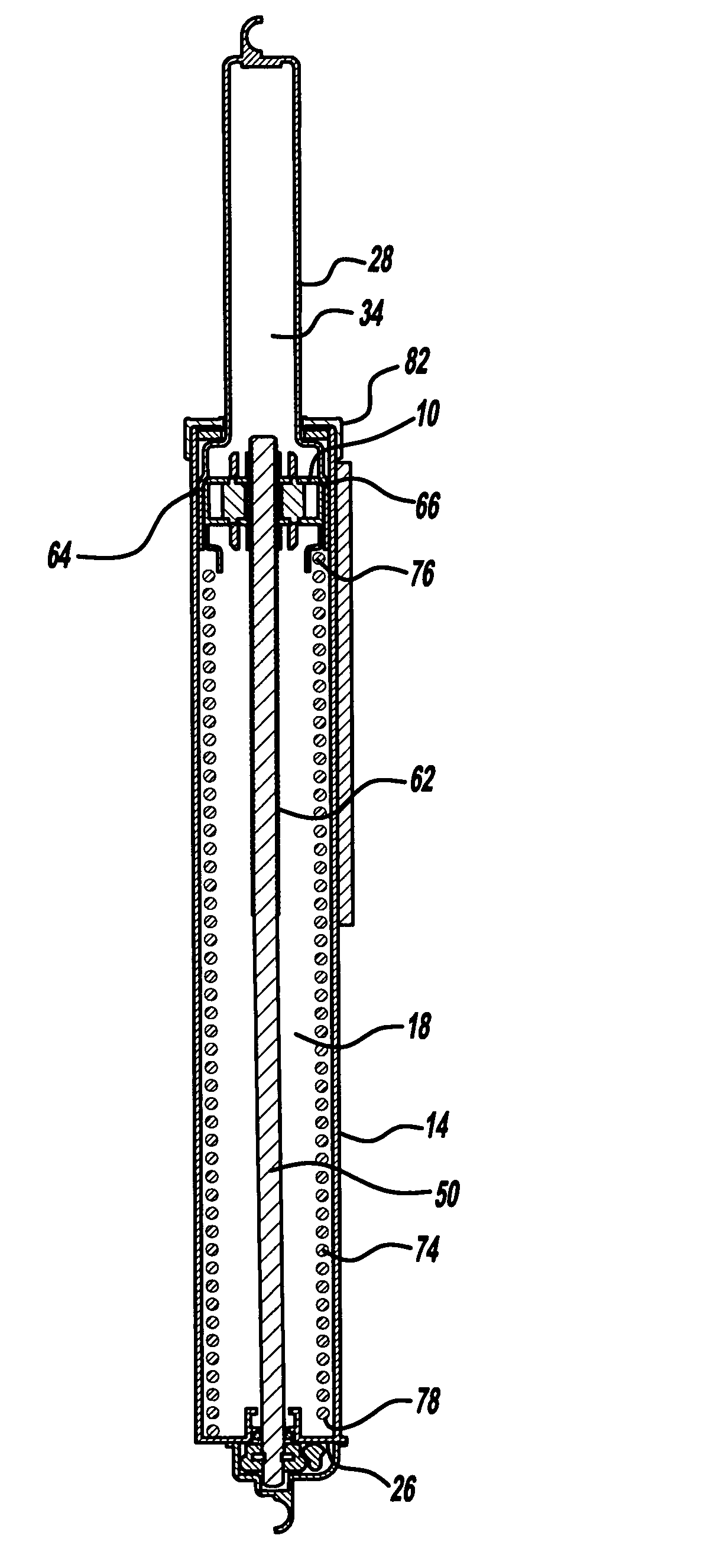
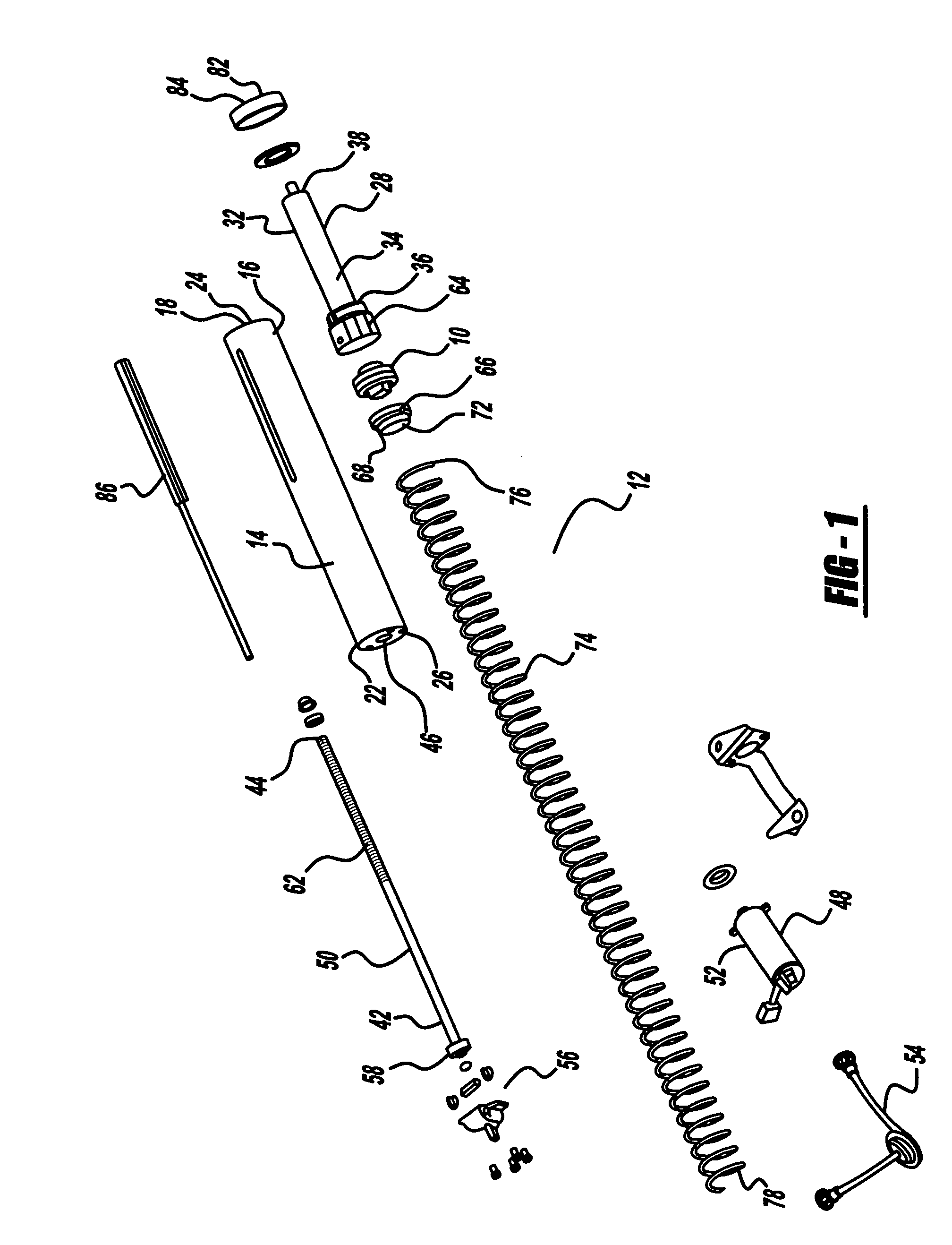
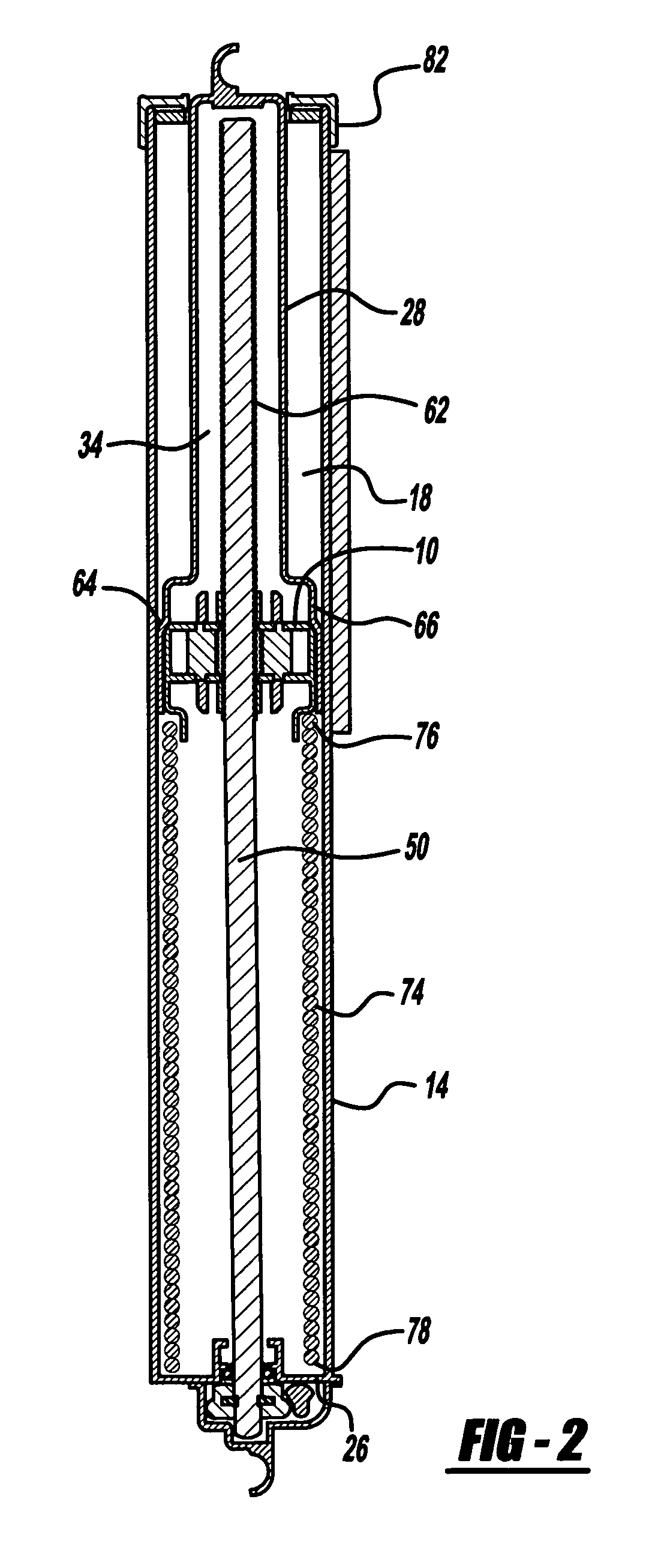
[0017]Referring to FIG. 1, there is shown a power strut assembly 12 according to the present invention. The power strut assembly 12 includes a first strut member 14 having joined outer walls 16 that define an interior cavity 18. The first strut member 14 extends from a first end 22 to a second end 24. The first end 22 includes a base wall 26 joined to the outer walls 16. The power strut assembly 12 also includes a second strut member 28 having joined outer walls 32 that define an interior cavity 34. The second strut member 28 extends from a first end 36 to a second end 38. The second strut member 28 is telescopically disposed within the interior cavity 18 of the first strut member 14. A lead screw 50 extends from a first end 42 to a second end 44 and is rotatively retained, allowing the lead screw 50 to freely rotate, at the first end 22 of the first strut member 14. The lead screw 50 extends into the interior cavities 18, 34 of the first and second strut members 14, 28. A clutch as...


PUM


Abstract

A power strut assembly for a vehicle includes a first strut member having joined outer walls that define an interior cavity. The first strut member extends from a first end to a second end. The first end includes a base wall joined to the outer walls. A second strut member also having joined outer walls defining an inner cavity extends from a first end to a second end. The second strut member is telescopically disposed within the interior cavity of the first strut member. A lead screw extends from a first end to a second end and is rotatively retained at the first end of the first strut member. The lead screw extends into the interior cavities of the first and second strut members. A clutch is retained by the second strut member and the lead screw is positioned to interact with the clutch. The clutch is movable between a disengaged position relative to the lead screw where the clutch is free to travel longitudinally relative to the lead screw and an engaged position wherein rotation of the lead screw translates to longitudinal motion of the second strut member relative to the first strut member.

Description

RELATED APPLICATION[0001]This application claims priority of U.S. Provisional Patent Application Ser. No. 60 / 732,735 filed Nov. 2, 2005, which is incorporated herein by reference.FIELD OF THE INVENTION[0002]The invention relates to powered drive assemblies, and with more particularity to a power strut assembly.BACKGROUND OF THE INVENTION[0003]Powered drive assemblies are known in the art and may be utilized for a multitude of applications. Such powered drive assemblies may be utilized for example as a powered lift gate strut. In such an application, the strut is linked to an electric motor and allows a user to open and close a lift gate of a vehicle remotely or using an electric motor. In such an application, the powered drive assembly includes a clutch to regulate engagement and disengagement of the power drive assembly. Known prior art clutches are typically large electromechanical devices that are expensive and require a large amount of packaging space within a vehicle. Additiona...

Claims


Application Information

Patent Timeline
Patent Type & Authority Patents(United States)
IPC IPC(8): F16F9/32
CPCE05F15/622E05F15/603E05Y2800/11E05Y2900/546Y10T74/18696Y10T74/18576Y10T74/18704
Inventor HANNA, RONALD J.SLUMBA, MICHAEL A.
Owner DURA GLOBAL TECH
Why Eureka
Try Eureka