Creation of a range image

a range image and image acquisition technology, applied in image data processing, instruments, surveying and navigation, etc., can solve the problems of insufficient allocation, difficulty in establishing the correspondence between pixels, and inability to compare the brightness ratio of images taken

Inactive Publication Date: 2010-09-28
VISIONTOOLS BILDANALYZE SYST
View PDF13 Cites 12 Cited by
  • Summary
  • Abstract
  • Description
  • Claims
  • Application Information

AI Technical Summary

Benefits of technology

[0123]Shading problems, such as they principally occur with stereo cameras, can be prevented or at least reduced by means of more than two cameras. Of course, in addition to these methods, the available cameras can also be used for conventional gray scale or color analysis.

Problems solved by technology

With stereo methods, the most difficult problem is to establish the correspondence between the pixels, i.e. to allocate the pixels of the one camera to the pixels of the other camera.
To establish correspondence, classic image analysis methods are used on the basis of the extraction of contour-like or blob-like features; however, due to possible problems in the extraction of features, an allocation found is not really certain; in addition, it must be estimated or interpolated between the features.
However, no random or pseudo random patterns are used, and there is also no indication for the comparison of brightness ratios of the images taken by two cameras.
This has the disadvantage that the textured elements can appear differently from different angles of view (sheen, shading, form).
As such, they are difficult to analyze and thus may provide uncertain results.
Consequently, these methods are only used on not excessively structured surfaces with a broad reflection club (mat surfaces).
It is disadvantageous in this respect that a) the brightness differs viewed from different directions and that b) these zo elements must have a certain expansion for a reliable analysis, which is why the acquisition of a pixel-wise correspondence again requires interpolation between the features.
One problem here is the high price for the projector which is realized e.g. by means of a linear variable wavelength filter.
It actually eases the requirement of a geometrically precise color projection, because random color patterns can thus be used; however, basic problems will remain with the color analysis.
Disadvantageous are the mechanical movement and the required precision in the projection.
A general disadvantage of methods with continuous, countercurrent illumination patterns over the field of vision is the fact that—with a planar base—the brightness values of neighboring pixels differ only slightly and a precise local allocation is therefore difficult.

Method used


Image

  • Creation of a range image
  • Creation of a range image
  • Creation of a range image

Examples


Embodiment Construction

[0142]Several embodiments according to the invention are described below on the basis of FIGS. 1 to 11; generally, those without mechanically moving components are preferred.

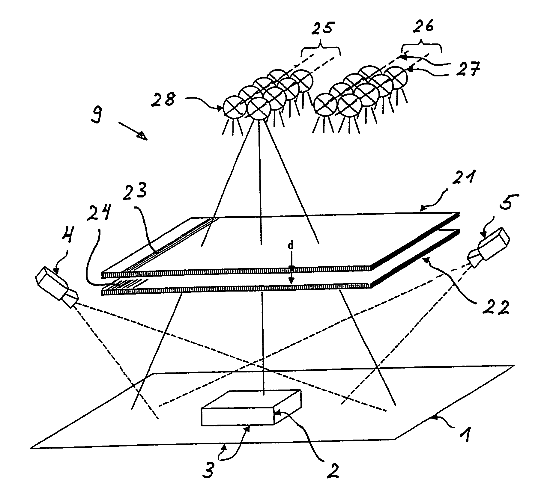
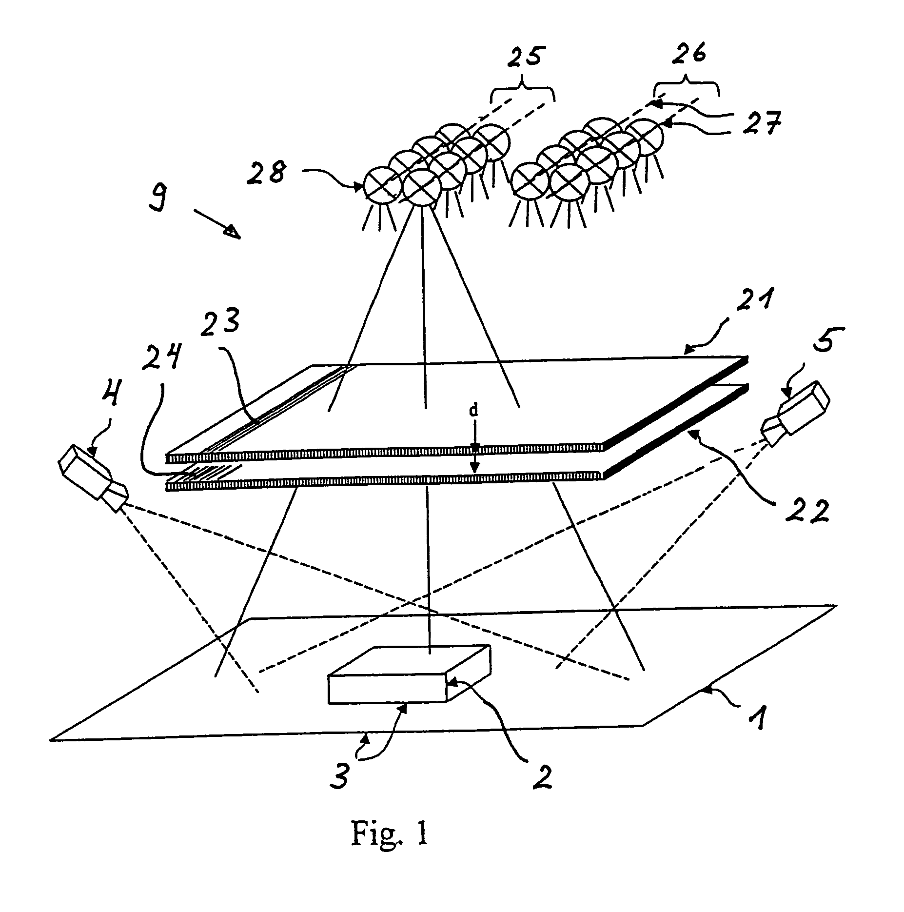
[0143]FIG. 1 shows such a preferred embodiment without movement of parts. As explained below in FIG. 8, the random patterns are here realized in moiré technique by superposition of two optical gratings 21, 22, with the grating constant varying in a pseudo random manner with at least one grating. According to the invention, the gratings 21, 22 have a distance d to each other so that with illumination from different directions different moiré patterns result, without a mechanical movement of the gratings 21, 22 being required.

[0144]In the example in FIG. 1, the strip grating structures 23, 24 are roughly arranged transversely to the epipolar lines so that the moiré random patterns also run roughly transversely to the epipolar lines. In the example, the mask of the top grating 21 is uniformly structured; the mask o...


PUM


Abstract

The most difficult problem in the creation of a range image with stereo cameras is the establishing of the correspondence of the points. For this, the scene is illuminated twice; thereof at least once with a random or pseudo random pattern. For both cameras, an image is taken for each of the illuminations and the quotient of brightnesses is calculated pixelwise. The correspondence is established on the basis of a comparison of the quotient of pixels on epipolar lines of different cameras. The illumination pattern is preferably highly modulated along the epipolar line; transversally or diagonally to it, it is not or only slightly modulated. For illumination, a projection unit is used which in a preferred arrangement comprises two superposed grating patterns which have a distance (d) to each other, with at least one varying in a pseudo random manner, and with two closely neighboring light sources which shine through the gratings and thereby generate different pseudo random patterns, especially moiré patterns. Applications are found, inter alia, in assembly control, robotics, metrology, archaeology, in the textile industry, in biometry, medicine, reverse engineering.

Description

BACKGROUND OF THE INVENTION[0001]The invention relates to a method and a device for the acquisition of a range image. In contrast to conventional images which code gray scales or colors, range images code the distance of object points from the sensor (usually a camera) or the height of the object points relative to a plane. The pixels of a range image thus comprise range information (e.g. distance or height) of each corresponding imaged object point. Technical applications are found, inter alia, in assembly control, in robotics, metrology, archeology, in the textile industry, in biometrics, medicine and reverse engineering.[0002]An overview of the methods used as well as a table of commercially available systems are found in the literature reference “Review of 20 years of range sensor development”, Journal of Electronic Imaging, 13 (1): 231-240, January 2004, National Research Council Canada. For more information about the methods, see also Paul J. Besl, “Active Optical Range Imagin...

Claims


Application Information

Patent Timeline
Patent Type & Authority Patents(United States)
IPC IPC(8): G01C3/00G01C3/08
CPCG01B11/2513G01B11/2545G01C11/06G06T7/0057G06T7/521
Inventor TROPF, HERMANN
Owner VISIONTOOLS BILDANALYZE SYST
Why Eureka
Try Eureka