Droplet deposition apparatus

a technology of droplets and deposition plates, which is applied in the direction of printing and inking apparatus, etc., can solve the problems of high ink volume, increase the mass of the print head, and consequentially the cost of the scanning carriag

Inactive Publication Date: 2010-10-05
XAAR TECH LTD
View PDF19 Cites 11 Cited by
  • Summary
  • Abstract
  • Description
  • Claims
  • Application Information

AI Technical Summary

Benefits of technology

[0014]It is an object of certain embodiments of the present...

Problems solved by technology

The high volume of ink also adds to the mass of the pri...

Method used


Image

  • Droplet deposition apparatus
  • Droplet deposition apparatus
  • Droplet deposition apparatus

Examples


Embodiment Construction

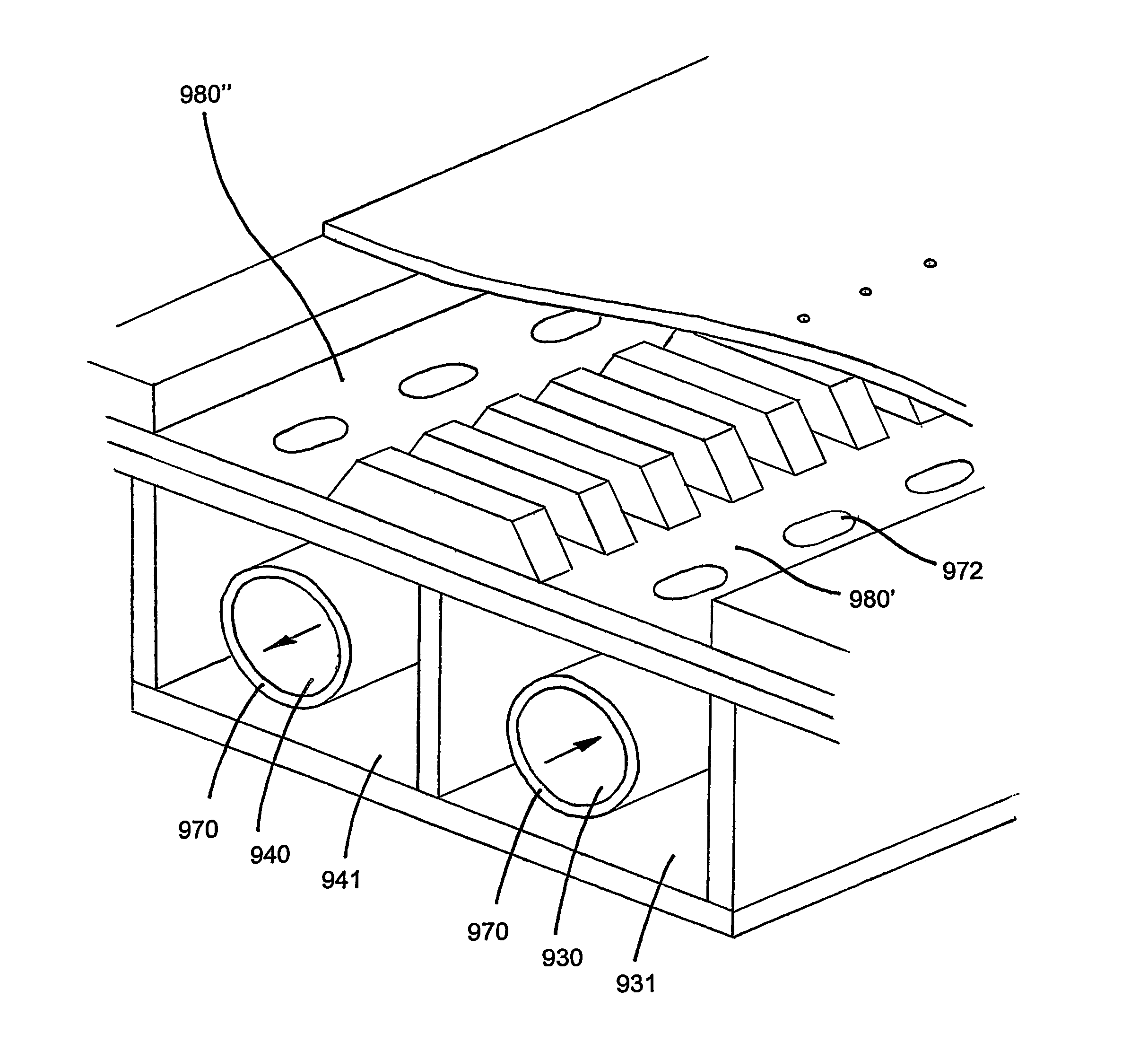
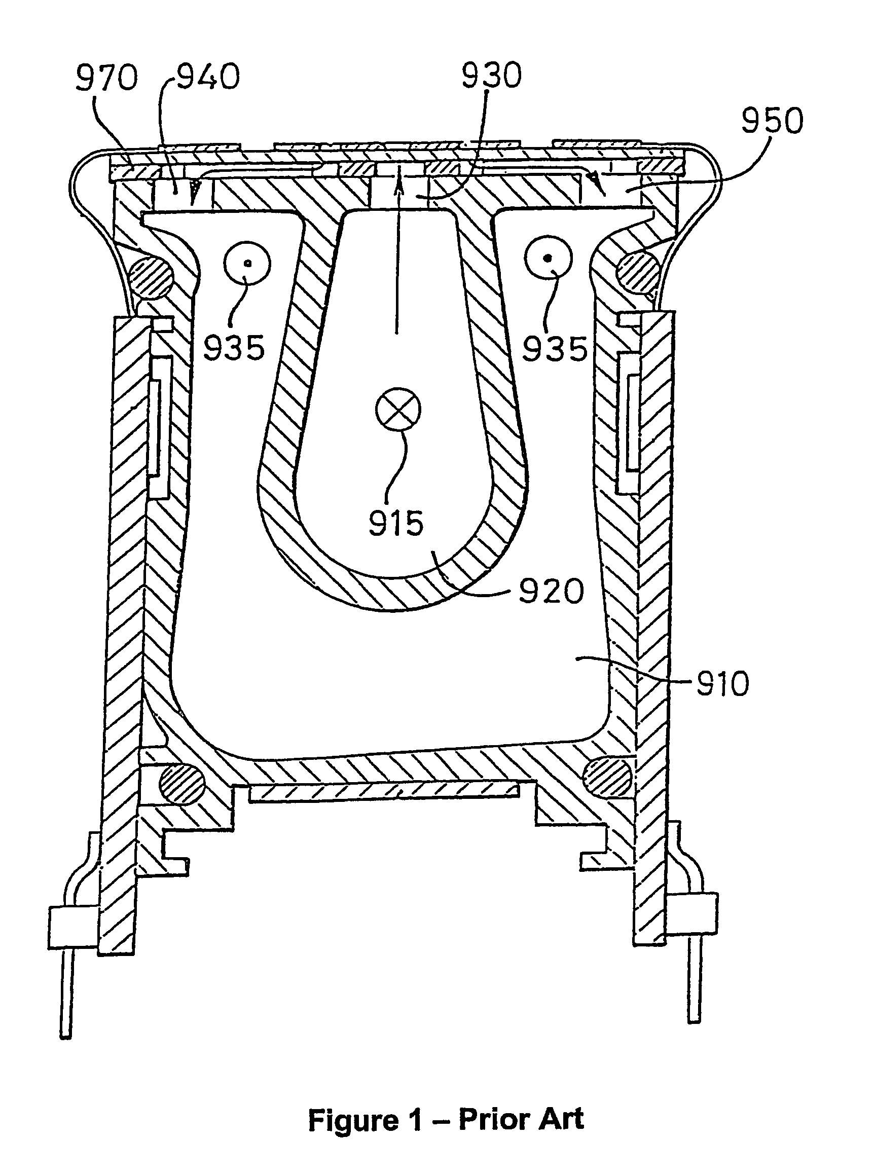
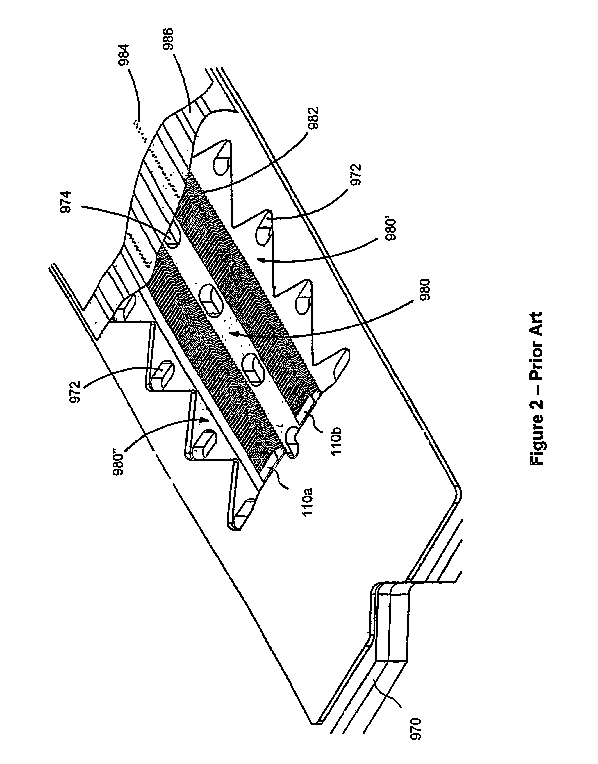
[0075]FIG. 1 depicts an ink supply support of an inkjet printer according to the prior art. The figure is a cross-section through a manifold structure that, in addition to controlling the flows of ink, provides support at its top surface for the piezoelectric elements that are actuable to eject ink through nozzles not shown in this figure. The piezoelectric elements are later described with reference to FIG. 2.

[0076]In FIG. 1, a central inlet manifold 920 has ink flowing in one direction (depicted as 915) along the length of the array. Conduits 930 formed in the top of the array and in a base plate 970 allow the ink to reach the pressure chambers (not shown) Ink is ejected through nozzles and the un-ejected ink is circulated to the outlet manifold 910 via two ports 940 and 950. Ink in the outlet manifold flows in the opposite direction 935 in order to minimise any thermal gradient over the length of the print head.

[0077]A positive pressure relative to atmospheric is established at t...


PUM


Abstract

Inkjet printhead with an array of ejection chambers spaced in an array direction, each communicating with an ink orifice, inlet and outlet plenum chambers communicating with the ejection chambers, and inlet and outlet manifolds extending in the array direction and communicating with the plenum chambers through a porous sheet. While there are substantial net ink flows in the array direction in the inlet and the outlet manifolds, there is substantially no net flow in the array direction in the inlet or outlet plenum chamber. Ink pressure is therefore constant over the array of ejection chambers.

Description

BACKGROUND OF THE INVENTION[0001]1. Field of the Invention[0002]2. Related Technology[0003]The present invention relates to droplet deposition apparatus and in particular to ink jet printers[0004]Ink jet printers are no longer viewed simply as office printers, their versatility means that they are now used in digital presses and other industrial markets. It is not uncommon for print heads to contain in excess of 500 nozzles and it is anticipated that “page wide” print heads containing over 2000 nozzles will be commercially available in the near future.[0005]It has been found that circulating ink through the print head when printing and when not printing has a beneficial affect on the droplet characteristics since the temperature may be controlled by a heat exchanger positioned outside the head.[0006]A further improvement taught in W000 / 38928 is to continually pass ink through the ejection chambers. This improves the reliability of the print head by, at high enough flow-rates, reduci...

Claims


Application Information

Patent Timeline
IPC IPC(8): B41J2/05B41J2/175B41J2/18B41J2/14
CPCB41J2/14032B41J2/14145B41J2/1433B41J2/17563B41J2202/12B41J2202/20B41J2/175B41J2/14
Inventor HARVEY, ROBERT A.MANNING, HOWARD J.
Owner XAAR TECH LTD
Why Eureka
Try Eureka