Photographic lens system and electronic imaging device using the same

a technology of electronic imaging device and lens system, applied in the field of photographic lens system, can solve the problems of difficult optical arrangement for and achieve the effect of facilitating correcting sagittal lateral aberration and facilitating adequate correction of sagittal lateral aberration

Active Publication Date: 2010-10-05
RICOH IMAGING COMPANY
View PDF5 Cites 0 Cited by
  • Summary
  • Abstract
  • Description
  • Claims
  • Application Information

AI Technical Summary

Benefits of technology

[0008]As a result of the inventor's study on the reasons why the correcting of sagittal lateral aberration is difficult, it is concluded that if each of the concave surfaces of the negative lens elements, provided on each side of the diaphragm as shown in FIG. 10, is provided with a strong negative refractive power, such an optical arrangement makes the correcting of sagittal lateral aberration difficult. Furthermore, it is found that if an intermediate (auxiliary) negative lens element having a weak negative refractive power is disposed between the above-mentioned concave surfaces of the negative lens elements, sagittal lateral aberration can be adequately corrected.

Problems solved by technology

As a result of the inventor's study on the reasons why the correcting of sagittal lateral aberration is difficult, it is concluded that if each of the concave surfaces of the negative lens elements, provided on each side of the diaphragm as shown in FIG. 10, is provided with a strong negative refractive power, such an optical arrangement makes the correcting of sagittal lateral aberration difficult.

Method used


Image

  • Photographic lens system and electronic imaging device using the same
  • Photographic lens system and electronic imaging device using the same
  • Photographic lens system and electronic imaging device using the same

Examples


embodiment 1

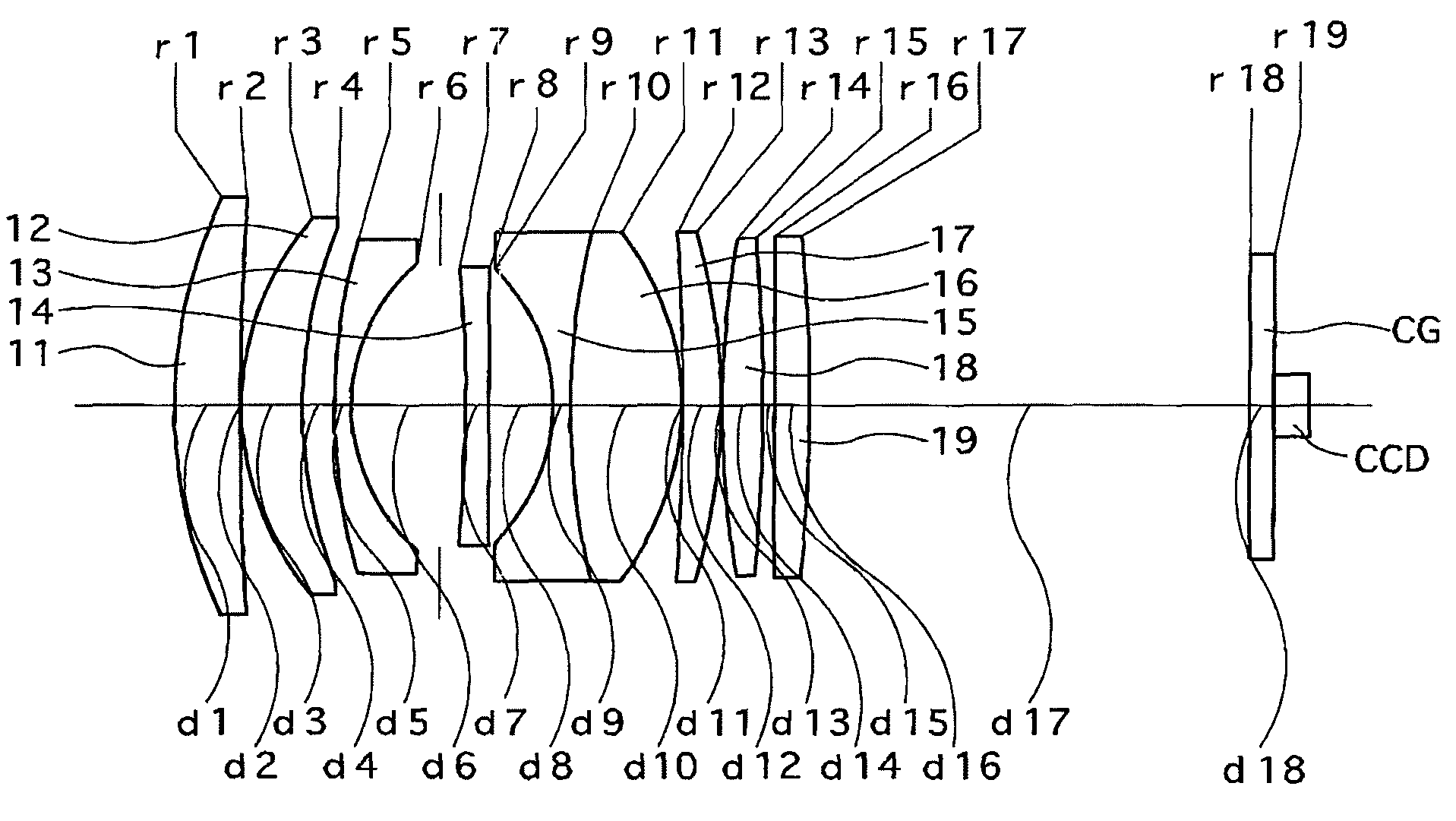
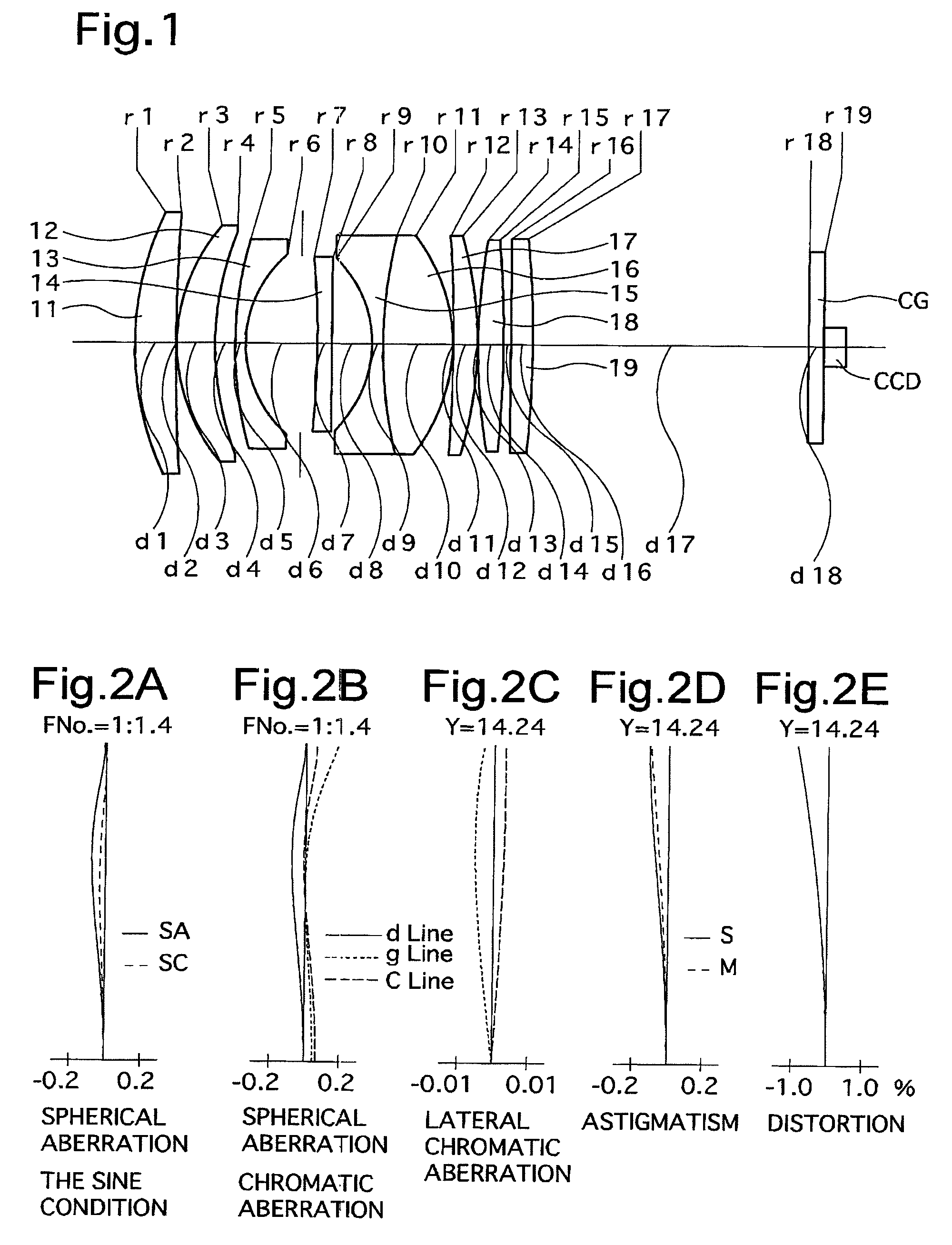
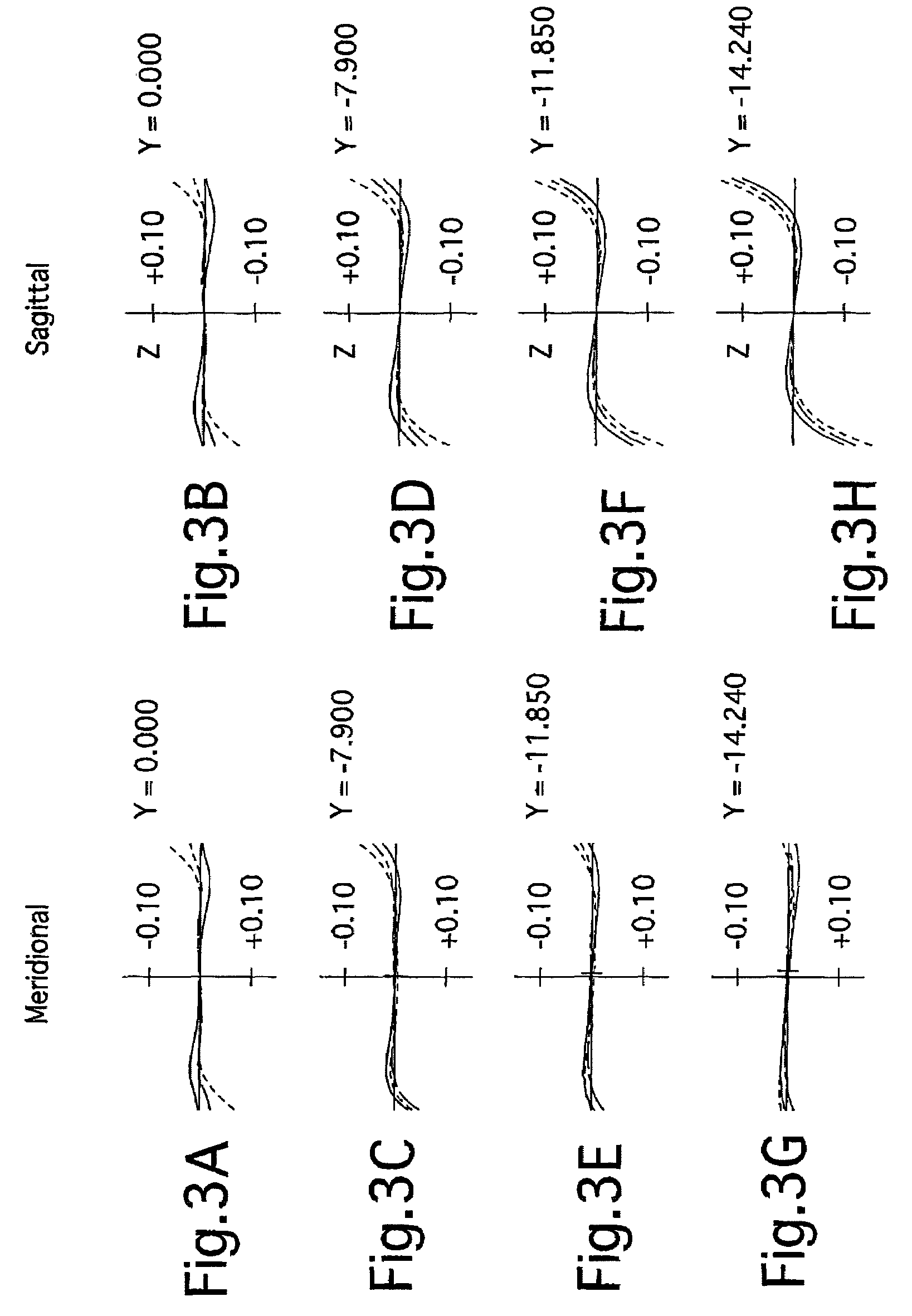
[0055]FIG. 1 shows the lens arrangement of the first embodiment of a photographic lens system according to the present invention. FIGS. 2A through 2E show aberrations occurred in the lens arrangement shown in FIG. 1 when an object at infinity is in an in-focus state. FIGS. 3A through 3H show lateral aberrations occurred in the lens arrangement shown in FIG. 1.

[0056]Table 1 shows the numerical data of the first embodiment.

[0057]The photographic lens system described in the following first through third embodiments has an angle-of-view of 14° which is more telescopic compared to a standard lens system (having an angle-of-view of, e.g., approximately) 23°).

[0058]The photographic lens system of the first embodiment includes a positive meniscus lens element 11 having the convex surface facing toward the object, a positive meniscus lens element 12 having the convex surface facing toward the object, a negative meniscus lens element 13 having the concave surface facing toward the image, a d...

embodiment 2

[0063]FIG. 4 shows the lens arrangement of a second embodiment of a photographic lens system according to the present invention. FIGS. 5A through 5E show aberrations occurred in the lens arrangement shown in FIG. 4 when an object at infinity is in an in-focus state. FIGS. 6A through 6H show lateral aberrations occurred in the lens arrangement shown in FIG. 4.

[0064]Table 2 shows the numerical data of the second embodiment.

[0065]The fundamental lens arrangement of the second embodiment is the same as that of the first embodiment.

[0066]The diaphragm S is provided 6.76 behind (on the image side of) the third lens element (negative meniscus lens element) 13 (surface No. 6).

[0067]

TABLE 2FNO. = 1:1.5f = 56.07M = −0.173W = 14.4fB = 0.0Surface No.rdNdν165.5694.321.7725049.62550.2080.10329.2805.741.8061040.9456.3203.22566.3921.411.6989530.1619.9988.357−150.0002.001.5814440.78∞5.449−20.0961.351.7618226.51065.0438.851.8340037.211−29.5630.1012−332.5323.551.7859044.213−65.7070.1014115.4513.461.77...

embodiment 3

[0068]FIG. 7 shows the lens arrangement of the third embodiment of a photographic lens system according to the present invention. FIGS. 8A through 8E show aberrations occurred in the lens arrangement shown in FIG. 7 when an object at infinity is in an in-focus state. FIGS. 9A though 9H show lateral aberrations occurred in the lens arrangement shown in FIG. 7.

[0069]Table 3 shows the numerical data of the third embodiment.

[0070]The fundamental lens arrangement of the third embodiment is that same as that of the first embodiment.

[0071]The diaphragm S is provided 6.80 behind (on the image side of) the third lens element (negative meniscus lens element) 13 (surface No. 6).

[0072]

TABLE 3FNO. = 1:1.4f = 56.36M = −0.173W = 14.3fB = 0.02Surface No.rdNdν154.3004.851.7725049.62373.7300.10329.9895.981.8061040.9453.3402.55566.7621.411.6989530.1619.4659.587−150.0002.001.5814440.78∞5.519−19.3801.501.7618226.51075.2109.421.8340037.211−29.2500.1012−244.6683.381.8061040.913−60.0000.1014110.0003.781.59...


PUM


Abstract

A photographic lens system includes a positive lens element, a positive lens element, a negative lens element having a concave surface facing toward the image, a diaphragm, a negative lens element having a concave surface facing toward the object, a positive lens element which is cemented to the negative lens element, and two or three positive lens elements, in this order from the object. An intermediate negative lens element, having the weakest negative refractive power out of all of the negative lens elements, is provided between the negative lens element having the concave surface facing toward the image and the negative lens element having the concave surface facing toward the object.

Description

BACKGROUND OF THE INVENTION[0001]1. Field of the Invention[0002]The present invention relates to a photographic lens system having an f-number of approximately 1.4 and a half angle-of-view of approximately 14°, and also relates to an electronic imaging device using the same.[0003]2. Description of Related Art[0004]FIG. 10 shows a photographic lens system according to the related art (e.g., Japanese Unexamined Patent Publication No. H06-242370) which is a comparative example and the subject of improvement by the present invention.[0005]The photographic lens system shown in FIG. 10 includes a positive lens element, a positive lens element, a negative lens element having a concave surface facing toward the image, a diaphragm, a cemented lens having a negative lens element having a concave surface facing toward the object and a positive lens element, and two positive lens elements, in this order from the object.[0006]However, in this comparative example, sagittal lateral aberration was ...

Claims


Application Information

Patent Timeline
Patent Type & Authority Patents(United States)
IPC IPC(8): G02B9/64G02B9/00G02B15/14
CPCG02B9/64G02B13/16
Inventor HIRAKAWA, JUN
Owner RICOH IMAGING COMPANY
Why Eureka
Try Eureka