Refill control mechanism for a liquid holding tank

a technology of liquid holding tank and control mechanism, which is applied in the direction of valve operating means/releasing devices, functional valve types, transportation and packaging, etc., can solve the problems of maintenance and repair problems, inconvenient and expensive service calls, and easy short-circuiting and malfunction

Active Publication Date: 2010-10-19
ACTION MFG
View PDF5 Cites 1 Cited by
  • Summary
  • Abstract
  • Description
  • Claims
  • Application Information

AI Technical Summary

Benefits of technology

[0003]It is therefore an object of the present invention to provide for an improved, nonelectric mechanism for automatically controlling the addition of liquid to a holding tank whenever the liquid in the tank falls below a threshold level.

Problems solved by technology

This type of valve has caused maintenance and repair problems.
Because the solenoid is installed in proximity to water, it is susceptible to short-circuiting and malfunction.
Frequent, inconvenient and expensive service calls are often required.

Method used


Image

  • Refill control mechanism for a liquid holding tank
  • Refill control mechanism for a liquid holding tank
  • Refill control mechanism for a liquid holding tank

Examples


Embodiment Construction

[0013]Other objects, features and advantages will occur from the following description of a preferred embodiment and the accompanying drawings, in which:

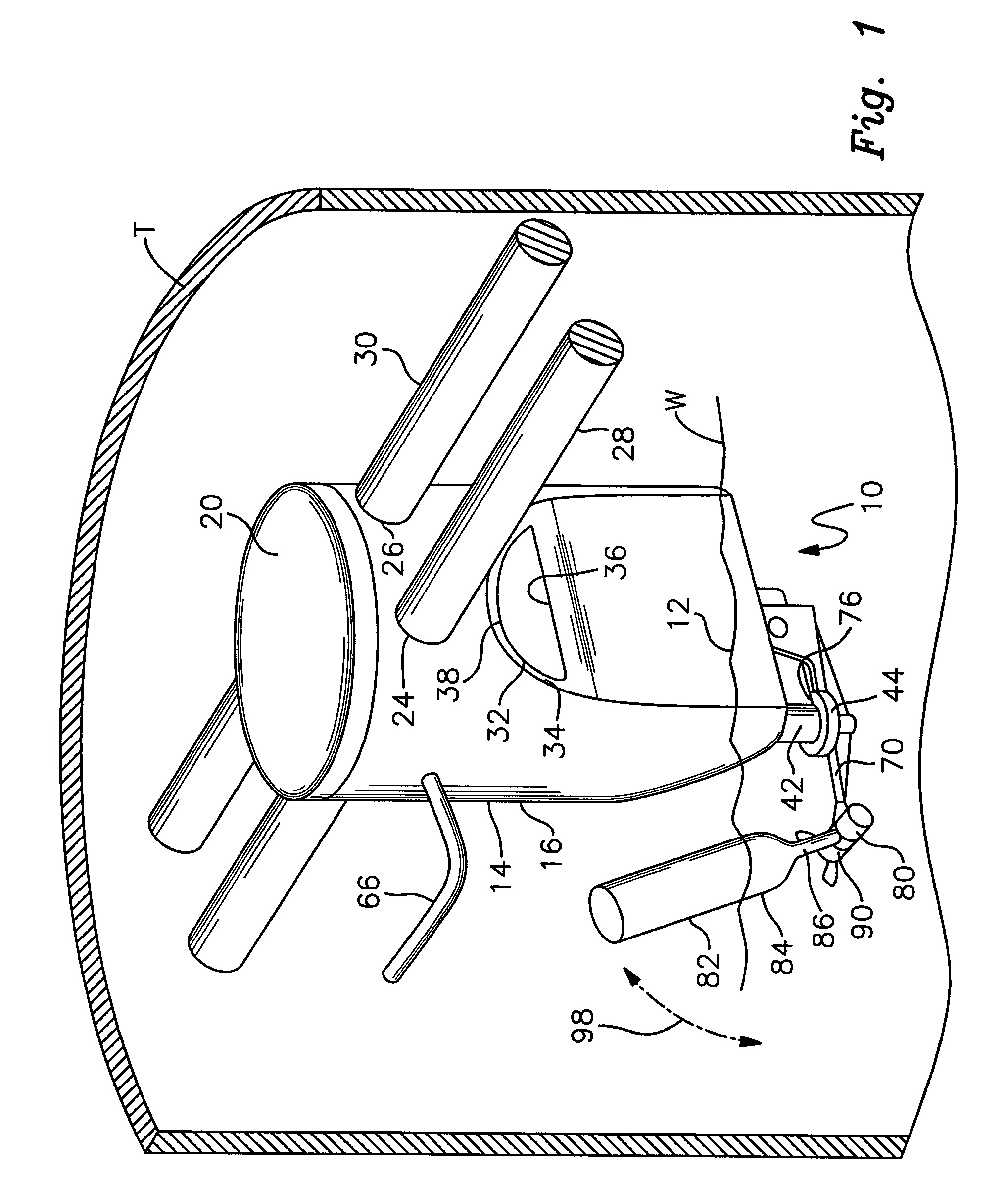
[0014]FIG. 1 is a perspective, partially cut away view of a liquid refill control mechanism in accordance with this invention;

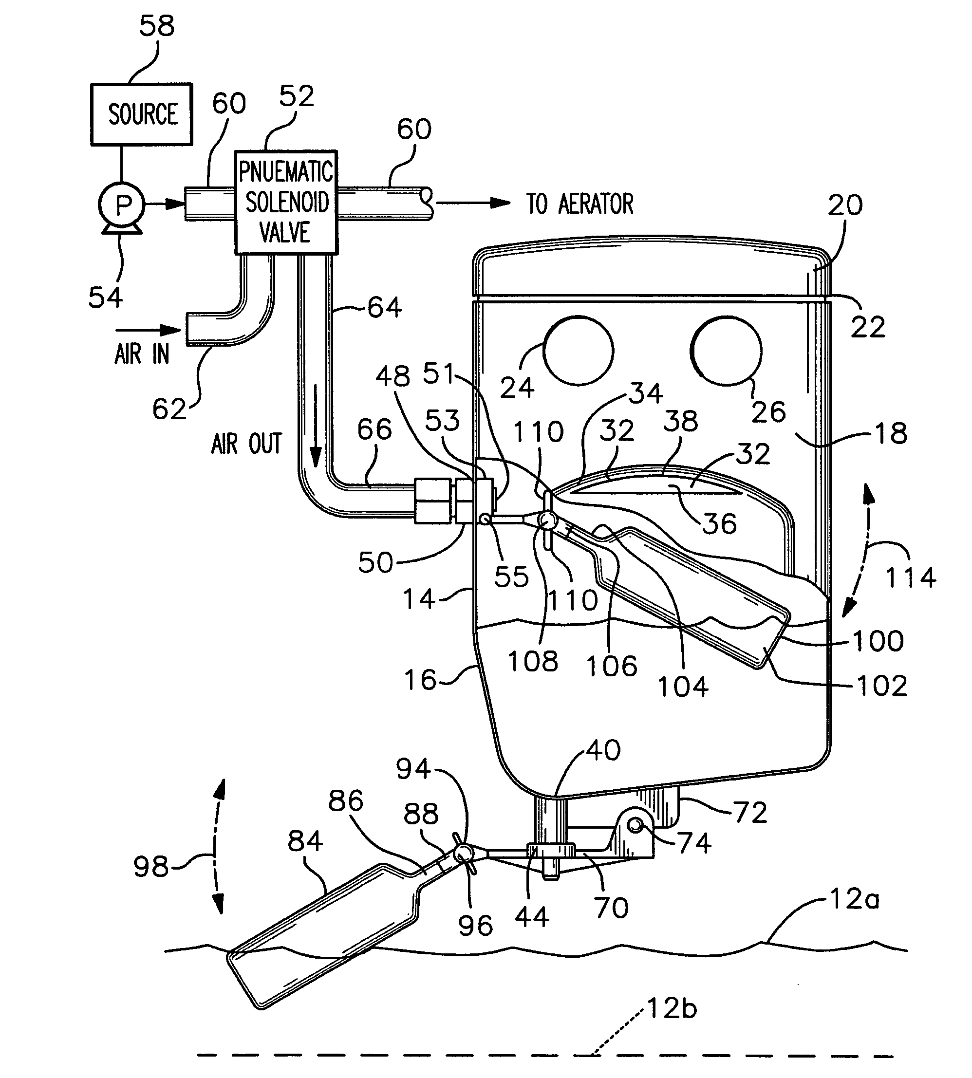
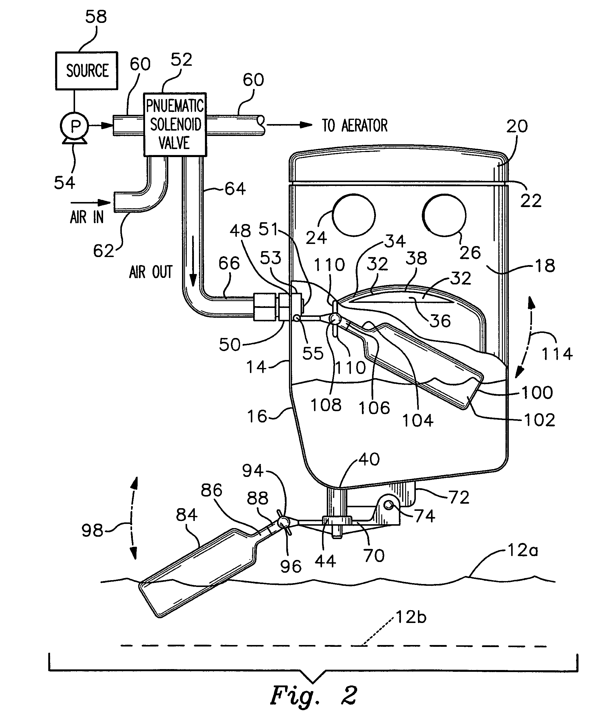
[0015]FIG. 2 is an elevational, cut away and partly schematic view of the control mechanism and an operably interconnected pneumatic solenoid valve for introducing water or other liquid into the holding tank with which the mechanism is used.

[0016]FIG. 3 is an elevational view of the liquid replenishment mechanism with its discharge valve in a closed condition;

[0017]FIG. 4 is a view similar to FIG. 3 with the discharge valve in an open condition; and

[0018]FIGS. 5 and 6 are front elevational views of an alternative mechanism according to this apparatus wherein the mechanism is employed for replenishing water in an R / O tank.

[0019]There is shown in FIGS. 1 and 2 a refill control mechanism 10 for automatically mai...


PUM


Abstract

A liquid refill control for a holding tank includes a pneumatic solenoid valve for delivering liquid to the tank in an open state and restricting delivery of the liquid to the tank in a closed state. The solenoid valve has a pneumatic exhaust. A container mounted in the tank includes an inlet for introducing liquid from the tank into the container and an outlet formed below the inlet. A discharge valve is operably mounted to the tank for alternately closing and opening the outlet. A lower float closes the discharge valve when the liquid is at or above a predetermined level in the tank and opens the discharge valve when the liquid is below the predetermined level to discharge liquid from the container. A pneumatic exhaust valve alternately opens and closes the pneumatic exhaust which in turn changes the state of the pneumatic solenoid valve. An upper float mounted in the container maintains the pneumatic exhaust valve in one of the open and closed conditions when the liquid in the container is at or above a threshold level and maintains that valve in the other condition when the liquid in the container is below the threshold level.

Description

FIELD OF THE INVENTION[0001]This invention relates to a mechanism for automatically controlling the addition of a liquid, such as water, to a holding tank. The mechanism may be employed for various liquid holding tanks such as aerated well water tanks, reverse osmosis (R / O) tanks and the like.BACKGROUND OF THE INVENTION[0002]Water holding tanks are commonly utilized to store well water. Recently, a water holding tank that utilizes a blow-molded construction has been introduced. See our copending patent application Ser. No. 10 / 794,013. Periodically, water must be added to the holding tank in order to refill the tank and / or to aerate the water in the tank so that it is safe for drinking. Most known holding tanks employ an electrically operated solenoid valve that is opened as needed to introduce water to the tank. This type of valve has caused maintenance and repair problems. Governmental codes presently require the electrical solenoid to employ a ground fault. Because the solenoid is...

Claims


Application Information

Patent Timeline
Patent Type & Authority Patents(United States)
IPC IPC(8): F16K31/18
CPCF16K31/26Y10T137/7319Y10T137/7413Y10T137/7371
Inventor SHEPHERD, RICHARD J.KLEIN, DANIEL A.
Owner ACTION MFG
Why Eureka
Try Eureka