
Video camera and remote recording system

a video camera and remote recording technology, applied in the field of video camera and remote recording system, can solve the problems of poor recorded sound quality, inconvenient running a cable from the camera to a separate microphone, and unsatisfactory methods of getting the microphone closer to the desired sound sour

Inactive Publication Date: 2010-10-19
CANON KK
View PDF15 Cites 5 Cited by
  • Summary
  • Abstract
  • Description
  • Claims
  • Application Information

AI Technical Summary

Benefits of technology

[0008]The present invention addresses this object to allow convenient recording using multiple audio and video sources that can be simply synchronized in a post-recording environment.
[0023](g) physically connecting the audio device to the video device, thereby causing audio data and associated or embedded time data stored on the audio device to be transferred to the video device.

Problems solved by technology

Such integrated microphones generally result in poor recorded sound quality, often in spite of the quality of the microphone itself, but primarily because the microphone is not usually positioned close to enough to the sound producing subject.
Existing methods of getting the microphone closer to the desired sound source are unsatisfactory in various ways.
For example, running a cable from the camera to a separate microphone can be inconvenient, potentially dangerous, and is often impractical.
Wireless microphones may be used but are expensive and unreliable.
If there is interference between the transmitter and receiver, audio information will often be lost or quality will be reduced.
Further, where an increasing number of wireless microphones are used in an area, for example by a number of people making a video recording, it is more likely that there will be interference or lost data.
However, the SMPTE time code system was created with the limitations of tape-based recording media in mind.
The sync tone repeats every twenty-four hours, however, so it is possible for the system to become confused if recording occurs over a longer period of time.
Also, synchronization can be awkward.
The inconvenience of recording the same sync tone on each device is too great for most amateur video recording artists.

Method used


Image

  • Video camera and remote recording system
  • Video camera and remote recording system
  • Video camera and remote recording system

Examples


Embodiment Construction

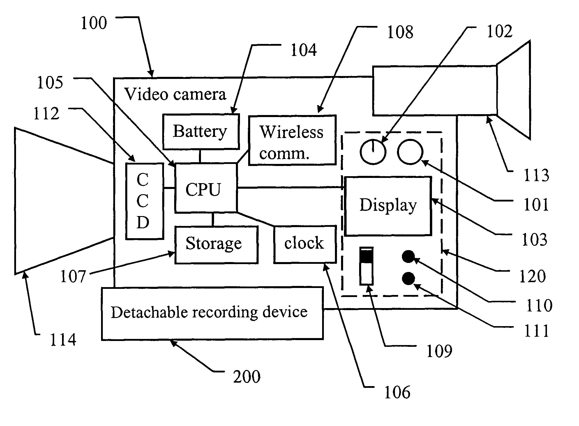
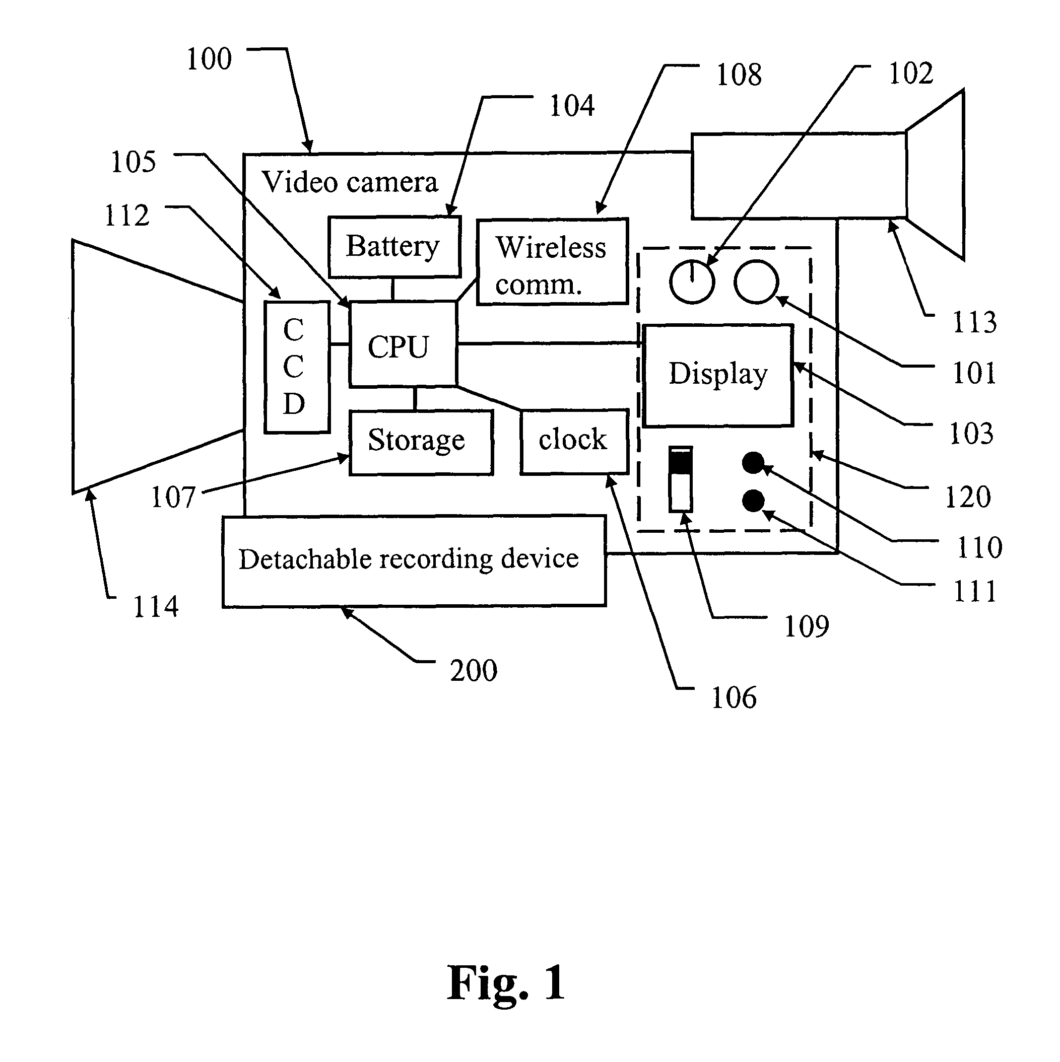
[0035]FIG. 1 shows a video camera device 100 capable of recording video and optionally audio data into a storage 107 thereof. The camera device 100 is preferably a digital video camera having a digital storage. Such affords the ability to non-linearly store metadata associated with recorded content. The camera device 100 has a lens 114 and a viewfinder 113 for viewing a scene to be recorded and a charge-coupled-device 112 for capturing a video representation of the scene. A central processing unit (CPU) 105 operates to control the camera device 100 and specifically to enable recording of video, audio and other information (data) in the storage 107. The camera device 100 also includes other interface features 120 such as, a record button 101, a display control jog dial 102 for editing control, a port 110 for wired connection to a remote audio recording device 200 or to another camera device 100, a port 111 for connecting to a pair of headphones facilitating private audio reproduction...


PUM


Abstract

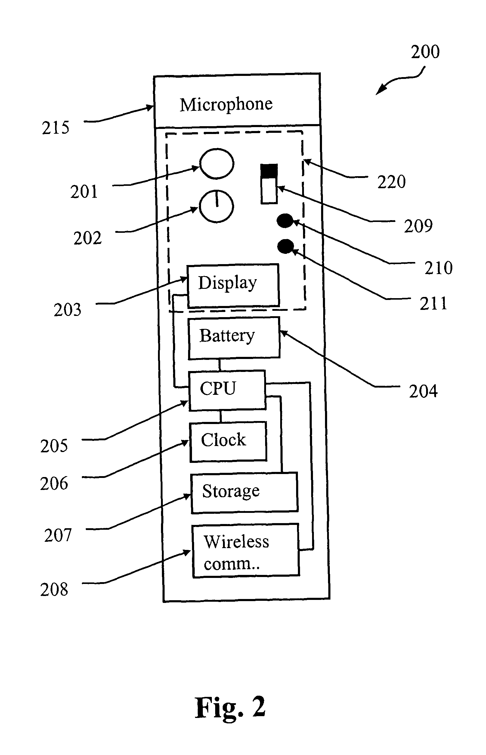
A system for recording audio and video comprises at least one video camera device (100), each camera device comprising a subsystem for capturing (112) at least video data, a storage device (107) upon which at least the video data is stored, a wireless interface (108) for communicating with at least one further recording device (200), an internal clock(106) for recording at least a time at which the video data was recorded, and a connecting port (108, 110) enabling connection to a remote-control device (eg. 200). The system also has at least one of the further recording devices (200), each comprising a microphone (215) for capturing audio information and a storage device upon which corresponding audio data is recorded, a wireless interface (208) for communicating with the video camera device, an internal clock (206) for recording at least a time at which the audio data was recorded, and a connection port (208,210) enabling connection to the video camera device.

Description

FIELD OF INVENTION[0001]The present invention relates to the recording of audio with a video camera and, in particular, to the usage and integration of a separated audio source.BACKGROUND[0002]Integrated microphones are found upon almost all video cameras in the marketplace and are used to record one or more audio tracks in synchronism with video images simultaneously recorded by the camera. Such integrated microphones generally result in poor recorded sound quality, often in spite of the quality of the microphone itself, but primarily because the microphone is not usually positioned close to enough to the sound producing subject. Typically such microphones are omnidirectional and detect much extraneous noise which is recorded along with the subject sound. Existing methods of getting the microphone closer to the desired sound source are unsatisfactory in various ways.[0003]For example, running a cable from the camera to a separate microphone can be inconvenient, potentially dangerou...

Claims


Application Information

Patent Timeline
Patent Type & Authority Patents(United States)
IPC IPC(8): H04N5/00H04N5/91
CPCG11B27/10H04N5/232H04N5/765H04N5/77H04N5/772H04N9/8205H04N23/661
Inventor SHELLSHEAR, ANDREW JOHN
Owner CANON KK
Learn More